As we are factory, we can guarantee our price is first- hand.
We have professional consultants to give you the most suitable solution.
Delivery time: 1-10 days after received the payment.
We have our own R&D team.
Support OEM/ODM.
MOQ : 1.
Product Details
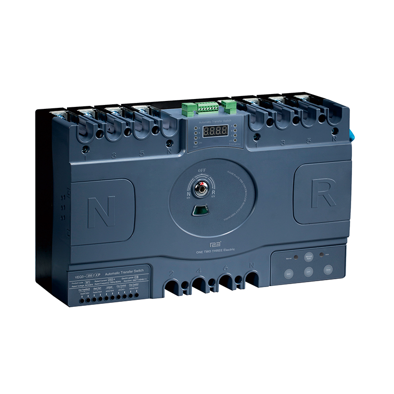
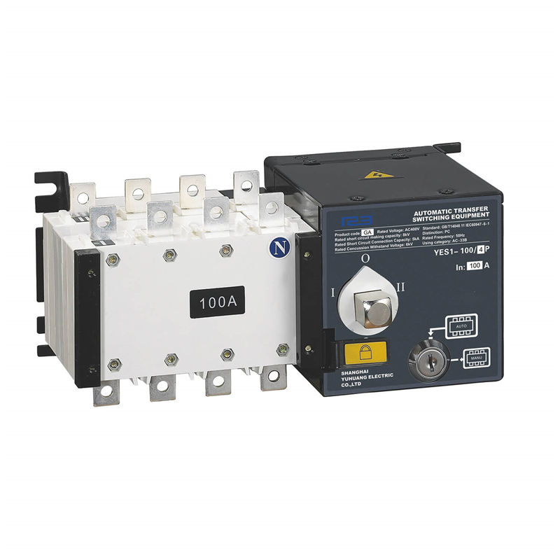
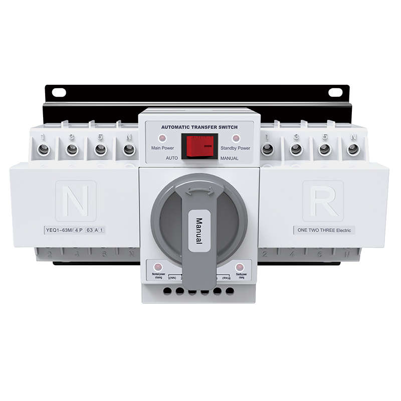
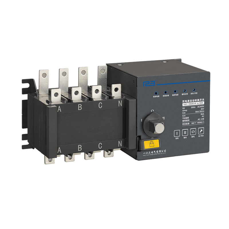
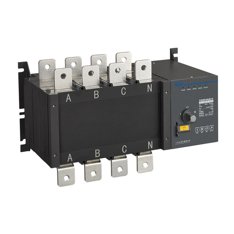
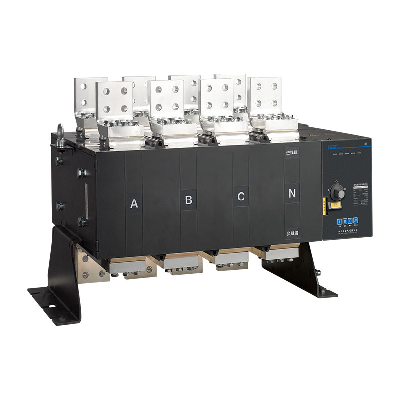
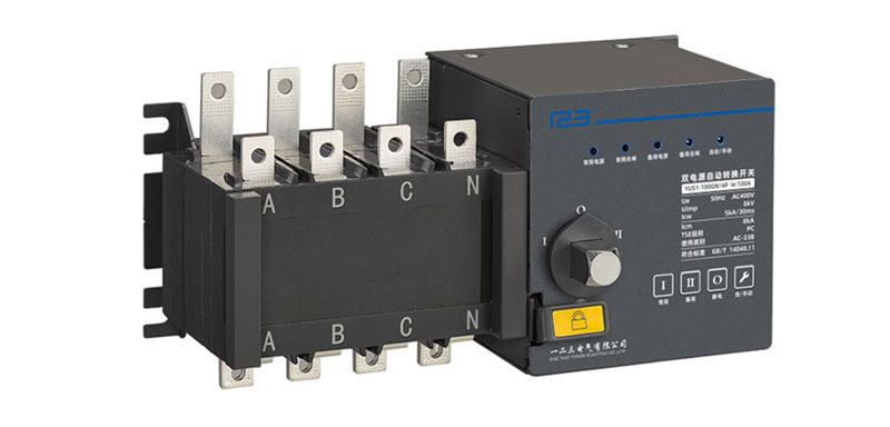
This series of double power automatic transfer switch is suitable for automatic transfer between two power sources in emergency power supply system with rated working voltage of 400V and below, rated frequency of 50/60Hz and rated current of 16A to 3200A, to ensure continuous, safe and reliable operation of important loads (such as fire fighting load). It is widely used in hospitals, shopping malls, banks, chemical industry, high-rise buildings, military facilities, fire protection and other important places where power cuts are not allowed.
Rated current: 16A~3200A
Pole: 4P
Automatic Transfer Switch Operating Manual
overview
This series of double power automatic transfer switch is suitable for automatic transfer between two power sources in emergency power supply system with rated working voltage of 400V and below, rated frequency of 50/60Hz and rated current of 16A to 3200A, to ensure continuous, safe and reliable operation of important loads (such as fire fighting load). It is widely used in hospitals, shopping malls, banks, chemical industry, high-rise buildings, military facilities, fire protection and other important places where power cuts are not allowed.
This product conforms to GB/T 14048.11 Low-voltage switchgear and controlgear-part 6-1: multi-functional electrical switch appliances-switching device, which is equivalent to IEC 60947-6-1: conforms to "high-rise civil building fire code", "building design fire code", "emergency lighting design guide", "civil building electricaldesign code", etc.
Performance and characteristics
Built-in sampling line is adopted for export products, so there is no need to add additional sampling line when customersuse them.
External safety seat for easy maintenance.
The intelligence type with full functions, the anti-interference ability strong cent shape and the economical reliable basic type are optional.
Full functions, with overvoltage, undervoltage and open phase switching function.
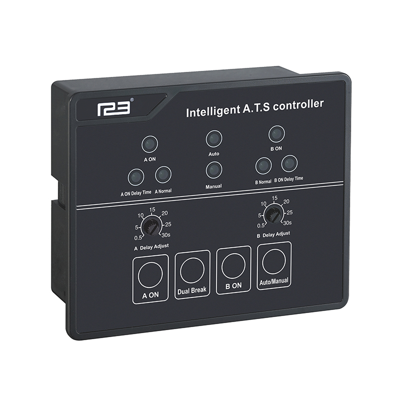
The intelligent controller adopts lC microcontroller as the control core, which has powerful function, easy expansion and strong anti-interference ability.
Double breakpoint horizontal pull mechanism is adopted in the mouth switch, which is safe and reliable in switching on and off.
The actuating load disconnecting switch is equipped with mechanical interlock device to ensure reliable operation of normal and standby power sources.
lt adopts the zero-position technology, which can be set to zero compulsivly in case of emergency(at the same time cut off the two standing power sources), and both meet the requirements of fire linkage.
lt has obvious on - off position indication, padlock and other functions, which can reliably realize the isolation of power supply and load.
Four operating functions: emergency manual operation, electric remote control operation, automatic control state emergency disconnect operation Automatic control operation.
Three stable working states (I-O-ll): common closing and standby opening; commonly opening, standby closing; common and standby power sources are both disconnected.
Normal working conditions
The operating environment temperature range is-25℃-+70℃, and the storage environment temperature range is -55℃-+85℃.
The elevation of the installation site shall not exceed 2000m.
The relative humidity of the air at the installation site should not exceed 50% when the ambient air temperature is +40℃. The relative humidity can be higher at a lower temperature. For example, when the average minimum temperature of the wettest month is +20℃, the average maximum relative humidity of that month can reach 90%. Appropriate measures should be taken to prevent condensation caused by temperature change.
Pollution level 3.
ATSE can be installed vertically or horizontally in the cabinet. Special orders are required for special requirements.
lt should be installed in a medium without explosion risk, and there is no enough gas and conductive dust in the medium to corrode the metal and damage the insulation.
lt should be installed in no rain and snow attack place.
Installation category (overvoltage category).
Installation category of switchgear for main circuit : lll.
Conversion controller and auxiliary circuit installation class: ll.
Product Parameters
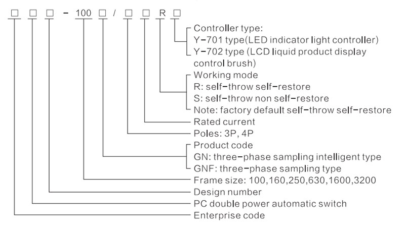
Model and its meaning
Main technical parameters
| Frame size | 100 | 160 | 250 | 630 | 1600 | 3200 | |
| Rated operating current le (A) | 16,20,25,32, 40,50,63,80,100 | 125,160 | 200,225,250 | 315,350,400, 500,630 | 800,1000 1250,1600 | 2000,2500 3200 | |
| Rated insulation voltage | 690V | 800V | |||||
| Rated impulse withstand voltage | 8KV | 12KV | |||||
| Rated working voltage | AC400V/50Hz | ||||||
| Use category | AC-33iB | ||||||
| Rated short circuit making capacity | 8KA | 17KA | 26KA | 67.5KA | |||
| Rated short time withstand current | 5kA/30ms | 10kA/60ms | 12.6kA/60ms | 32kA/60ms | |||
| Switching time | 2.5s | 1.2s/2.5s | 1.2s | 1.8s | 2.4s | ||
| Rated short circuit pulse current | Frount fuse 50KA | Front fuse 90KA | |||||
| Note. 630 frame productiont operation time is divided into 1.2s (series motor), 2.5s (synchronous motor) | |||||||
Switch structure description
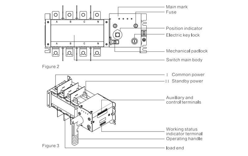
(1) Electrical key lock: electrical key lock control circuit power, open, the switch to achieve automatic and remote operation, closed, the switch can only be manuallyoperated.
(2) Operating handle: the electrical lock must be closed when operating the switch with operating handle.
(3) Mechanical padlock: when maintenance, first use the operating handle to make the switch in the state of "O off" state, then pull up the mechanical hang.
(4) Position indication: mark the working position of the switch (l common use, O power off, ll standby).
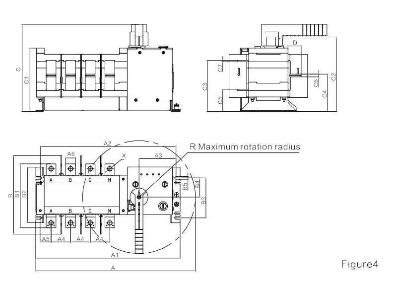
Appearance and installation dimensions
16A-250A mounting dimensions (two in and one out)
400~1600A lnstallation size (two in and one out)
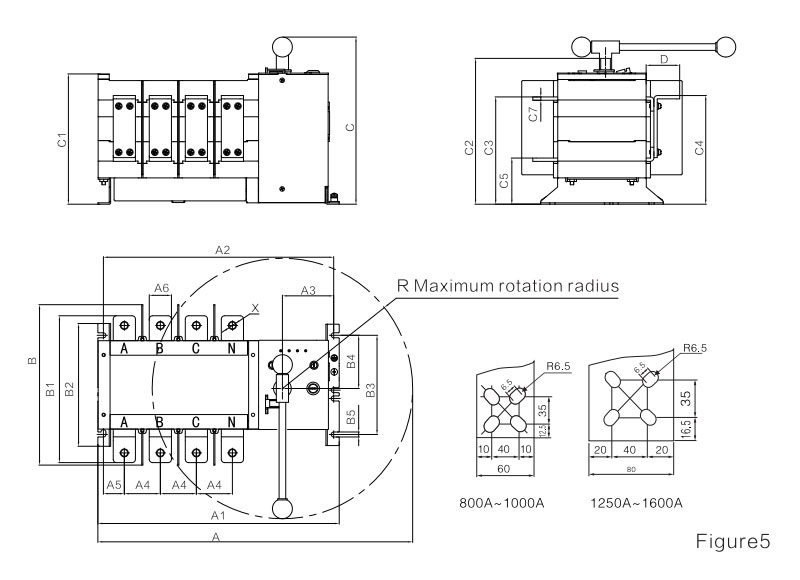
16A-1600A mounting size (two in and one out)
| Specifications | Shape and mounting dimension | |||||||||||||||||||||||
| A | A1 | A2 | A3 | A4 | A5 | A6 | B | B1 | B2 | B3 | B4 | B5 | C | C1 | C2 | C3 | C4 | C5 | C6 | C7 | D | X | R | |
| 16-100A | 268 | 260 | 241 | 96 | 30 | 12 | 14 | 145.5 | 110.5 | 103 | 84 | 44 | 7 | 170 | 118 | 143 | 92 | 67.5 | 40.5 | 5 | 2.5 | 22.5 | 6.7 | 115 |
| 125-160A | 344 | 304 | 283.5 | 94.5 | 36 | 19.3 | 20 | 185.5 | 140 | 127.5 | 102 | 49 | 7 | 223 | 163 | 189 | 129 | 94 | 56.5 | 7 | 3.5 | 30 | 9 | 144 |
| 200-250A | 408 | 368.5 | 347 | 94.5 | 50 | 28 | 25 | 200.5 | 163 | 141.5 | 102 | 106.5 | 7 | 223 | 162 | 186 | 130.5 | 97 | 56.5 | 7 | 3.5 | 34 | 11 | 144 |
| 400/3P | 510 | 375.5 | 355.5 | 92.5 | 65 | 38 | 32 | 289.5 | 248.5 | 221.5 | 179 | 96 | 9 | 303 | 235 | 266.5 | 192.5 | 193 | 82.5 | - | 5 | 52 | 11 | 235 |
| 400/4P | 570 | 435.5 | 415.5 | 92.5 | 65 | 38 | 32 | 289.5 | 248.54 | 221.5 | 179 | 96 | 9 | 303 | 235 | 266.5 | 192.5 | 193 | 82.5 | - | 5 | 52 | 11 | 235 |
| 630/3P | 510 | 375.5 | 355.5 | 92.5 | 65 | 38 | 40 | 289.5 | 265 | 221.5 | 179 | 96 | 9 | 303 | 235 | 266.5 | 193.5 | 196 | 83.3 | - | 6 | 60.5 | 12.5 | 235 |
| 630/4P | 570 | 435.5 | 415.5 | 92.5 | 65 | 38 | 40 | 289.5 | 265 | 221.5 | 179 | 96 | 9 | 303 | 235 | 266.5 | 193.5 | 196 | 83.3 | - | 6 | 60.5 | 12.5 | 235 |
| 800-1000/3P | 785 | 524 | 499 | 87 | 120 | 56 | 60 | - | 352 | 250 | 220 | 115.5 | 11 | 395 | 309 | 338 | 254 | 254 | 109 | - | 8 | 88 | - | 360 |
| 800-1000/4P | 1080 | 638 | 613 | 87 | 120 | 60 | 60 | - | 352 | 250 | 220 | 115.5 | 11 | 395 | 309 | 338 | 254 | 254 | 109 | - | 8 | 88 | - | 540 |
| 1250A/3P | 785 | 524 | 499 | 87 | 120 | 56 | 80 | - | 368 | 250 | 220 | 115.5 | 11 | 395 | 309 | 338 | 254 | 254 | 109 | - | 8 | 100 | - | 360 |
| 1250A/4P | 1080 | 638 | 613 | 87 | 120 | 60 | 80 | - | 368 | 250 | 220 | 115.5 | 11 | 395 | 309 | 338 | 254 | 254 | 109 | - | 8 | 100 | - | 540 |
| 1600A/3P | 785 | 524 | 499 | 87 | 120 | 56 | 80 | - | 376 | 250 | 220 | 115.5 | 11 | 395 | 309 | 338 | 255 | 255 | 110 | - | 10 | 108 | - | 360 |
| 1600A/4P | 1080 | 638 | 613 | 87 | 120 | 60 | 80 | - | 376 | 250 | 220 | 115.5 | 11 | 395 | 309 | 338 | 255 | 255 | 110 | - | 10 | 108 | - | 540 |
2000A~3200A Installation size of 2000a-3200a (two in and one out)
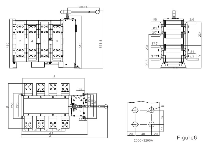
| Specifications | Shape and mounting dimension | |||||||
| A | A1 | B | G | J | T | V | Y | |
| 2000/3P | 785 | 541 | 422 | 360 | 499 | 10 | 56 | 212 |
| 2000/4P | 1080 | 655 | 422 | 540 | 613 | 10 | 60 | 212 |
| 2500A/3P | 785 | 541 | 432 | 360 | 499 | 15 | 56 | 217 |
| 2500A/4P | 1080 | 655 | 432 | 540 | 613 | 15 | 60 | 217 |
| 3200A/3P | 785 | 541 | 442 | 360 | 499 | 20 | 56 | 222 |
| 3200A/4P | 1080 | 655 | 442 | 540 | 613 | 20 | 60 | 222 |
Usage method
1. Use method of GN single phase sampling basic auxiliary terminal
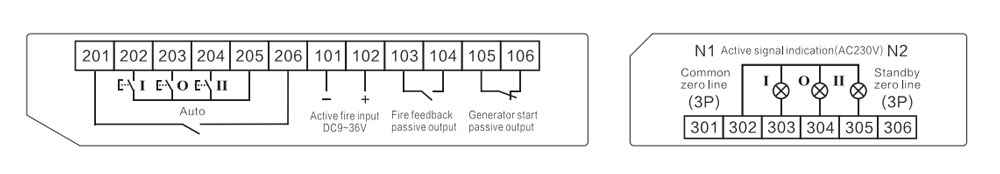
The terminals of, 201, 206 shall be short-connected with wires for remote control (cabinet door control conversion), and the disconnection shall be automatic.
205 is the remote COM port.
When the closed signal is detected at port 202, 205, the "ll stand by power" is normal , and the product is converted to the "ll standby" position.
When the closed signal is detected at ports 205 and 204, the product will switch tothe "ll standby" position if the "ll standby power" is normal.
When the closed signal is detected at ports 205 and 203, the product will switch to the "O power off "position if one or two of the " l common power supply "or "ll backup power supply" are normal.
Port 101, 102 is the fire-fight power supply DC24V (9-36V,101 is negative, 102 ispositive, polarity should not be reversed) input, the product will perform the fire linkage function.
Port 103,104 is the feedback signal output after the product performs the fire linkage function, a group of passive signal dry contacts.
Port 105,106 is the generator start signal. Connect this port to the generator controller to realize the generator start and stop control.
The work zero line input of 3P: 301 is the common zero line, 306 is the standby zeroline.
302 is the COM terminal of position indicating signal.
303 is "I common" position indication signal, active 220VAC.
304 is the "O power off" position indication signal, active 220VAC.
305 is "ll standby" position indication signal, active 220VAC.
2. GN3 three-phase sampling intelligent auxiliary terminal usage
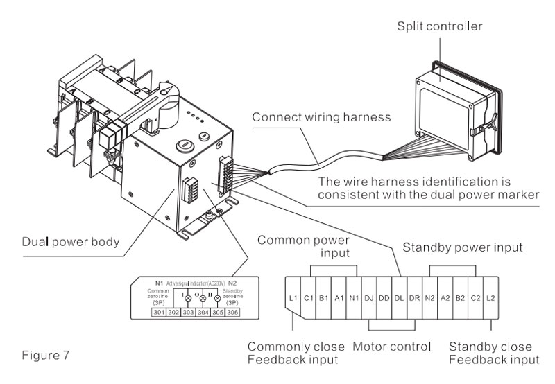
Usage of auxiliary terminal
lnsert one end of the configured connection harness into the corresponding port of the dual power body terminal and the other end into the corresponding port of the controller in line sequence.
302 is the COM terminal of position indicating signal.
303 is the "I common" position indicator signal, active 220VAC.
304 is the "O power off" position indication signal, active 220VAC.
305 is the "ll standby" position indicator, active 220VAC.
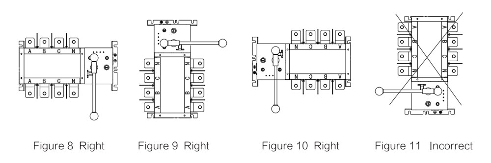
Correct installation method of switch
Product Choice
| Model | Type | ||||
| YES1-100GN | YES1-250GN | YES1-630GN | YES1-1600GA | YES1-3200GA | |
| Rated Current(A) | 16~100 | 125~250 | 315~630 | 800~1600 | 2000~3200 |
| Rated Insulation Voltage | 690V | 800V | |||
| Rated Impulse with Stand Voltage(KV) | 8 KV | 12 KV | |||
| Rated Working Voltage | AC400V | ||||
| Usingzation Category | AV - 33iB | ||||
| Rated Limited Short-Time with Stand Current | 8KA | 17KA | 26KA | 67.5KA | |
| Rated Short-Time with Stand Current | 5KV/30ms | 10KA/60ms | 12.6KA/60ms | 32KA/60ms | |
| Transfer Time | 2.5s | 1.2s-2.5s | 1.2s~2.4s | ||
| Control Power Voltage | DC24V、48V、110V AC220V | ||||
| Vote Number | Double Throw | ||||
| Wiring Manner | Panel Mounting | ||||
| Pole | 4P | ||||
Precautions
Switch wiring instructions
1. See figure 3 for primary wiring.
2. This series of dual-power transfer switches have built-in sampling lines,so customers do not need to sample from the main circuit.
3. this series of double power switch for two in one out, if the customer needs two in two out or one in two ready.
4. The left closing indicator terminal of this series of dual-power transferswitches is active 200VAC output, no need for the customer to report the power.
5. The standard connection harness of GN3F series dual-power transfer switch is 2m, and the customer can make remarks according to the need when placing an orderLonger.
Common faults and troubleshooting
| Fault | Reason | Processing method |
| Cannot transfer automatically | The neutralline is not connected for 3 poles | Corresponding position connection |
| Abnormal voltage and open phase | Check and repair power supply | |
| The split—type controller connector is loose | Re-fit tight | |
| wrong connection of common and standby power | Correct. Re-access correctly | |
| The electrical key is in manual mode | As for automatic position | |
| The mechanical padlock is lifted or not in place | Check and put in place | |
| The remote port 201 and 206 are in short一circuit condition | Check and disconnect |
Common faults and troubles hooting methods that may be encountered in the process of debugging oruse should be operated according to the above table. lf the fault cannot be eliminated, please timely contact our after-sales service.
Switch debugging description
1. The installation and debugging of the product shall be carried out by professionals and those who are familiar with the switch equipment operations.
2. The corresponding protection and preventive measures should be considered before debugging. The connection mode of the switch main loop must make the lead wire free from any pressure or strong action.
3. Before debugging, check whether the switch is not damaged or has any other harmful environmental impact, and check whether the wire head should be loose during transportation; Clean up dirt, especially on the surface of insulation.
4. When connecting the primary circuit, it should be noted that the phase sequence of the main and standby power must be consistent; when connecting the secondary control circuit, it should be operated strictly in accordance with the instructions; when the switch is installed, it must be well grounded.
5. After the product is installed, the power will be turned off. Take out the special operating handle supporting the product and turn it from the usual to the standby, and then from the standby to the three cycles in common use.
6. Check the wiring and secondary loop at a time, after confirmed, the products are in a common location, were used and the standby power supply, and then disconnect common power supply, the product after a delay the transformation to the standby power, restore common power supply, then after time delay shall be returned to the common power supply (except since couldn't from complex), three loop operation and each time interval of more than 20s.