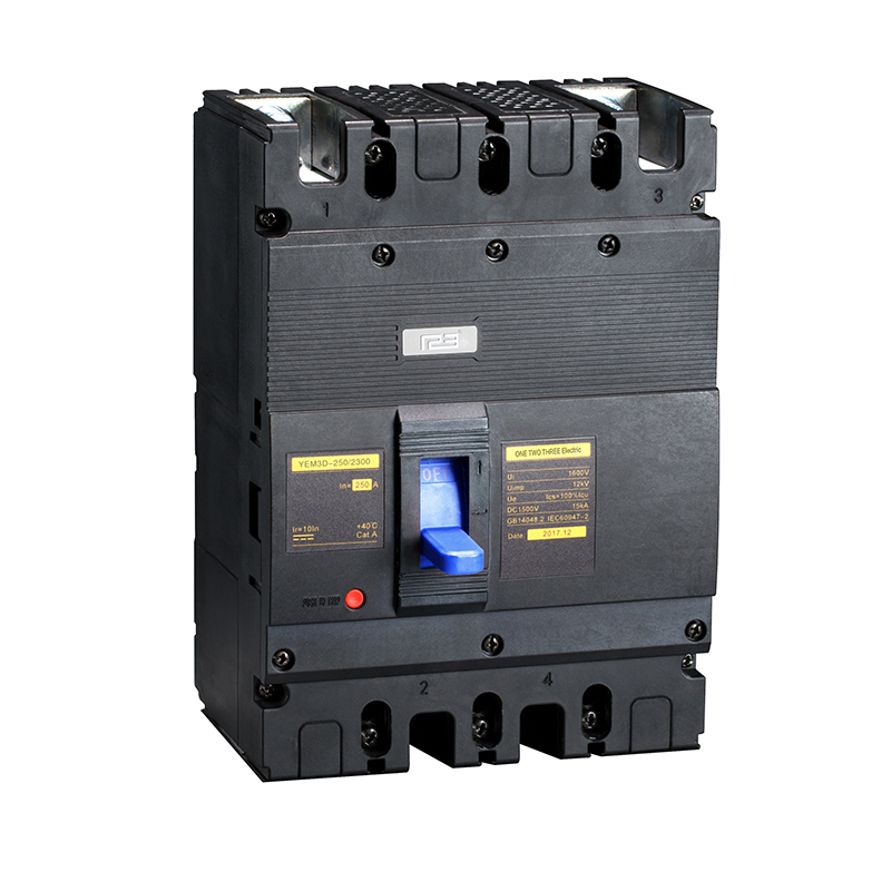
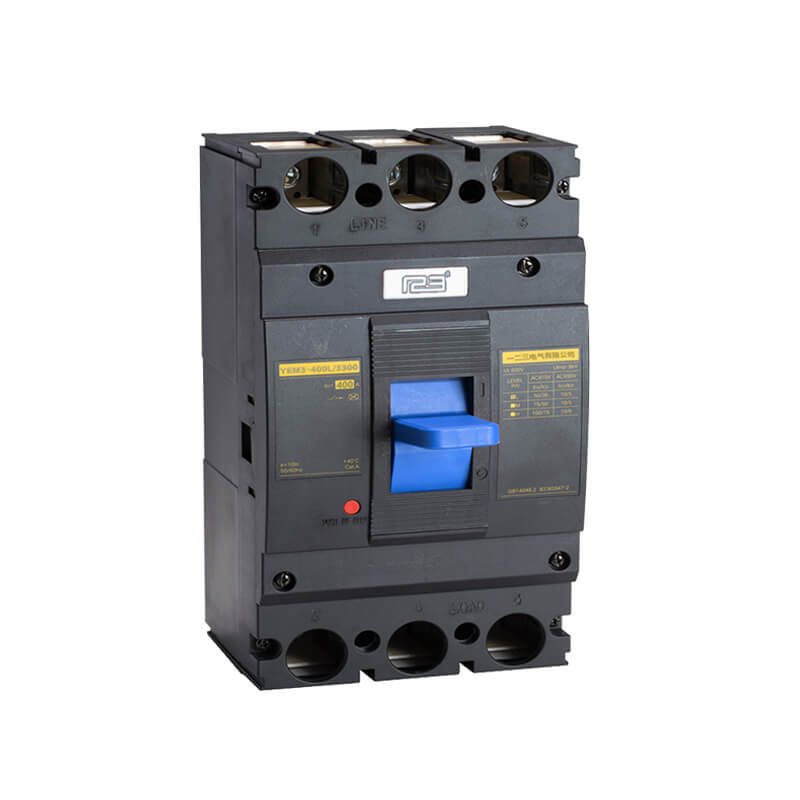
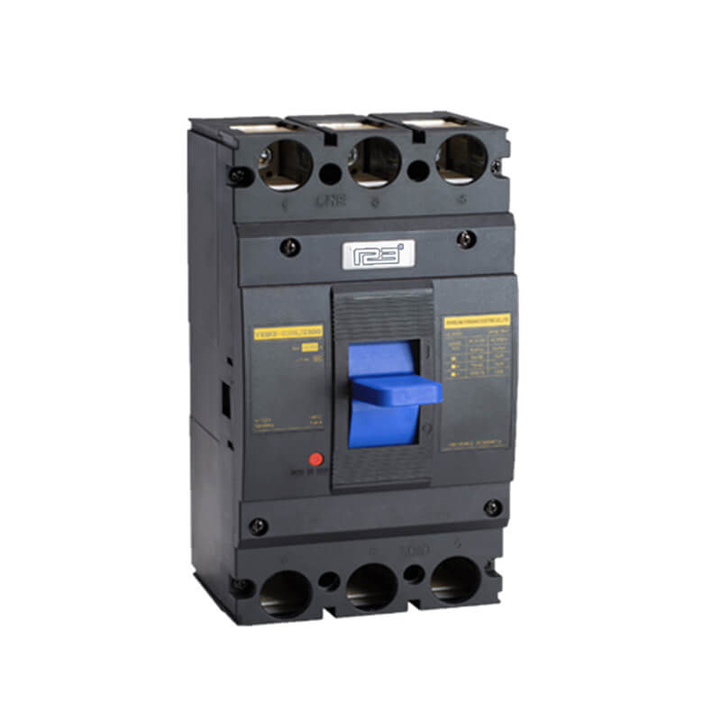
Product Details
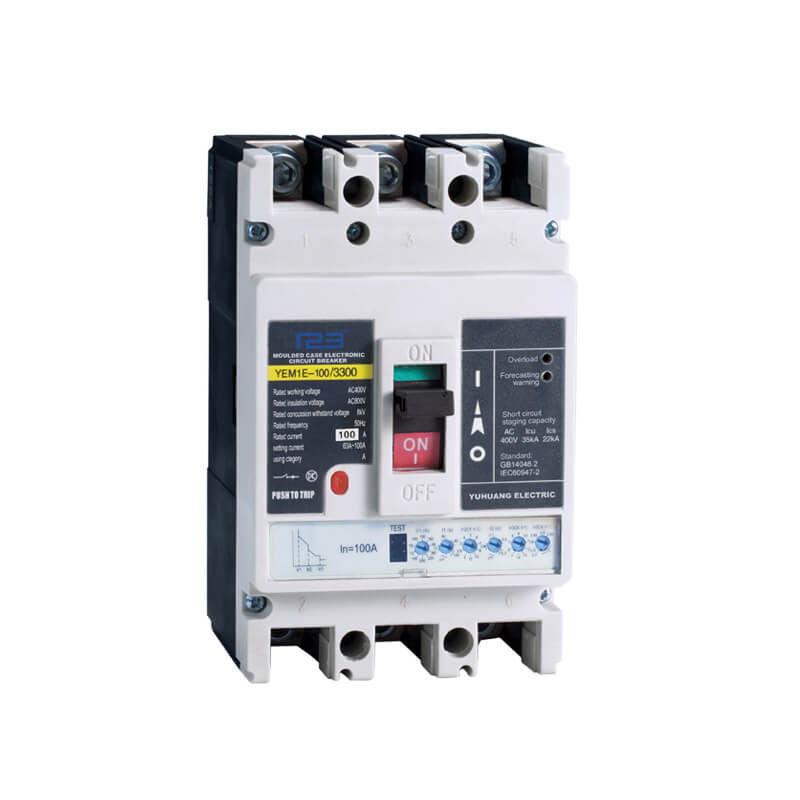
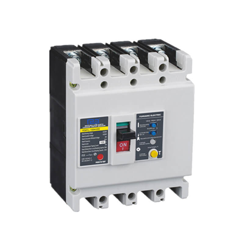
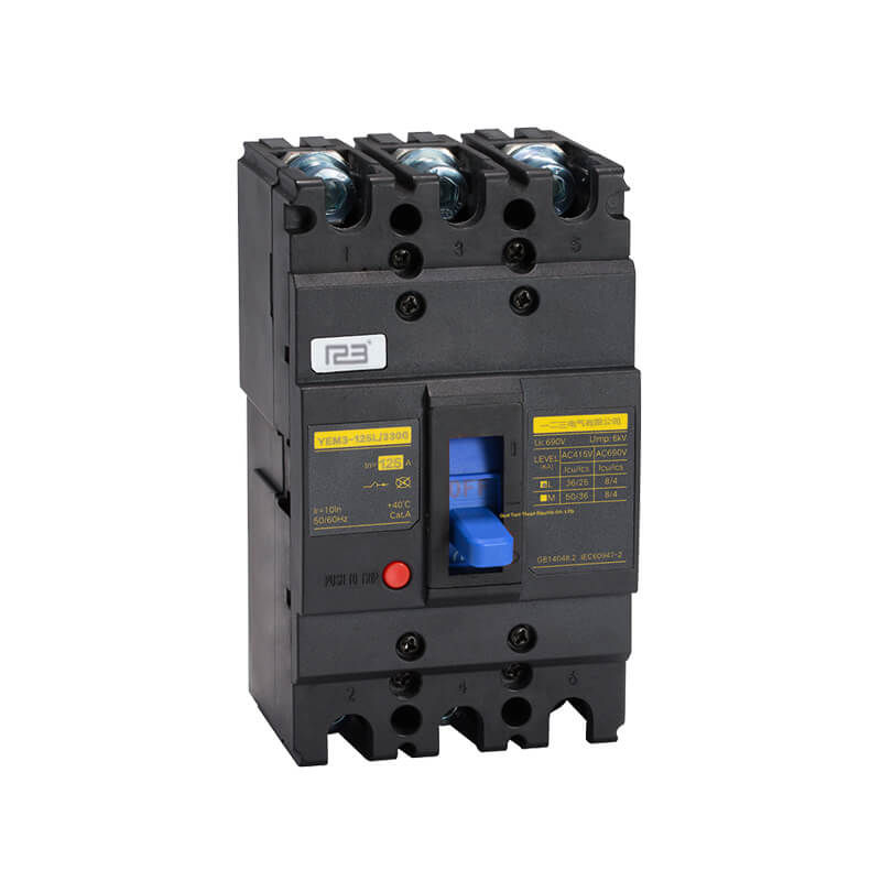
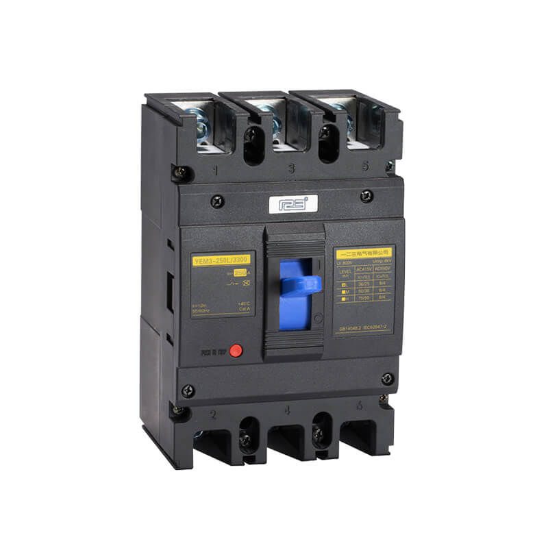
Circuit breaker has over-load,short circuit and under-voltage protection function so that protects the circuit and power supply device from being damaged.
Rated current: 125A~800A
Pole: 3P,4P
Moulded Case Circuit Breaker Operation Instructions
Thank you for using the M3 series molded case circuit breaker of ourcompany.Please read this operation instruction carefully beforeinstallation, circuit connected, operation, maintenance,to insure theproper use.
Installation attention
 warning
• Please do the operation according to the relevant provisionsrequired, to avoid major accident.
⚠Note
• Please according to relevant clause to operate,to avoid accidentor matter breaker.
About install
warning
• Please install it on the metal or some flame retardant things.
• Do not install it in the environment of containing gas explosion, otherwise it will explode danger.
• Do not install it in the moist environment.
⚠Note
• Do not install it in the external magnetic field is 5 times large thenthe geomagnetic field place,otherwise the breaker can't worknormally.
• Do not install it in the place of gas medium can corrode metal anddestroy the insulation.
• Rotate the operating mechanism,it need order from our companyto ensure quality.
lf user buy the part by yourselfe, please select reliable Otherwise, the company can not be responsible for any adverse consequences after assembly.
Relevant wiringw
Warning
• Must be wired by qualified personnel,Make sure that the input power is completely disconnected before you can perform wiring.
• Must be wired after install body.
• Circuit breaker wiring must comply with the rule of up input and down output, that is 1、3、5 wiring termination connect with power line, 2、4、6 wiring termination connect with Load line, No allowed to confuse.
Relevant operation
warning
• Wet hands can not operate circuit breaker, or possible will happen he electric shock accident.
⚠Note
• Do not operate the circuit breaker frequently ,or will shorten the life of circuit breaker.
• The circuit breaker go with Under-voltage release, the release should be electricity, then allow the circuit break.
• lf the circuit breaker installed with shunt release, the circuit breaker should be switch on, then supply the shunt release with rated voltage, circuit breakers should be reliable release.
Relevant maintenance and inspection and part change
Warning
• Maintenance and inspection must need professional technicians to perform.
• User select the inside or outside part, it need buy form our company to quality assurance, if user buy the part from other company or modified products, The company will not be responsible.
Relevant matters of before using
Notes before you check the box
• When you received the circuit breaker you purchased, please check the following items. check the appearance whether there are some losses occurred in the course of the transport. such as the damaged shell, and so on.
• In the box, there are not only the circuit breaker body, working instructions, product certification, but also have the screws, nuts, and parts, please check one by one in the packing list.
Product Parameters
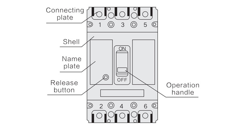
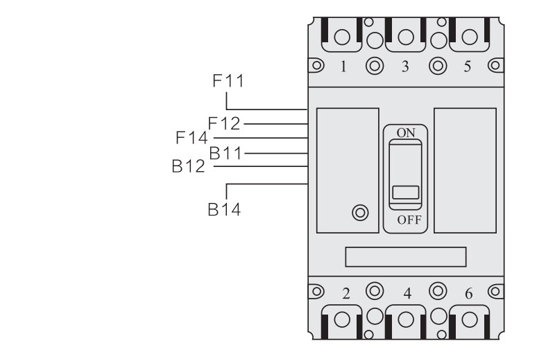
The appearance of the product and the name of the parts
Storage environment
| ltem | Specification |
| Ambient temperature | -25℃~+55℃ |
| Relative humidity | (When the environmenttemperature is 25) ≤95% |
lnstallation
Insulation test
According to the standards, the circuit breaker need to take the insulation test before out of factory. Because the circuit breaker has the electronic circuit boards. lf you want to retest, must according tothe following steps:
a. use 1000VDC megger.(M3-63, use 500VDC)
b. lnsulation resistance should be not less than 20MQ.
d. Link the under-voltage release of circuit breaker to the inputline and the shell.
lf the users do not have megger, can replace it with frequencyvoltage tester.add voltage 2000Vlmin.
Using environment
The environmental requirement where the circuit breaker install
| Ambient temperature | -5℃~+40℃,and average of 24h is not morethan 35℃. |
| Relative humidity | When the temperature is 40℃, do not morethan 50%, in the most wet month, the averagecan not higner than 25℃, and also the biggest average relative humidity can not more than 90 %, thinking the change of the temperature when the frost on surface of the products |
| Altitude | No more than 2000m |
| Pollution | 3 Class |
Tripping characteristics of switching MCCB
| Rated current of release (A ) | Thermodynamic release (ambient temp 40℃ ± 2℃) | Operational current of magnetic release (A) | |
| 1.05In (Cold state) inoperative time(h) | 1.3In (Cold state) inoperative time(h) | ||
| ln≤63 | ≥1 | <1 | 10ln ± 20% |
| 63≤ln≤250 | ≥2 | <2 | |
| 250≤In≤800 | ≥2 | <2 | 5In ± 20%10 In ± 20% |
Notes: The instantaneous action value of the rated operating current ln=10A-40A ofthe circuit breaker is the same as that of ln=50A
Tripping characteristics of overload protection MCCB
| Rated currentof release (A) | Thermodynamic release (ambient temp 40℃) | Operational current of magnetic release(A) | |||
| 1.0In (Cold state) inoperative time (h) | 1.2In (Cold state) inoperative time (h) | 1.5In (Cold state) inoperative time (h) | 7.2In (Cold state) inoperative time (h) | ||
| ln≤250 | ≥2 | <2 | <4min | 4s<Tp≤10s | 5ln±20% 10ln±20% |
| 250≤ln≤630 | <8min | 4s<Tp≤20s | |||
Notes: The instantaneous action value of the rated operating current In=10A-40A of the circuit breaker is the same as that of ln=40A
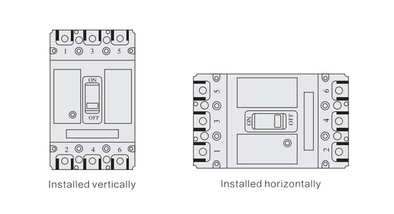
Installation method
Circuit breaker can be installed vertically, but also horizontally
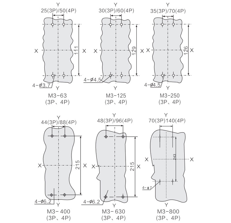
□ The pening of Installation board
□ Front board wiring
X-X、Y-Y is the center of the circuit breaker
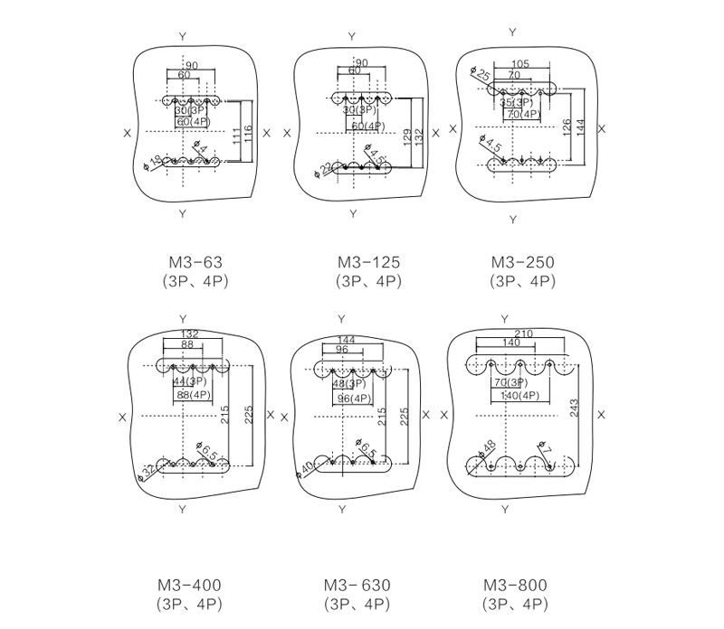
□ Back board wiring
X-X Y-Y is the center of the circuit breaker
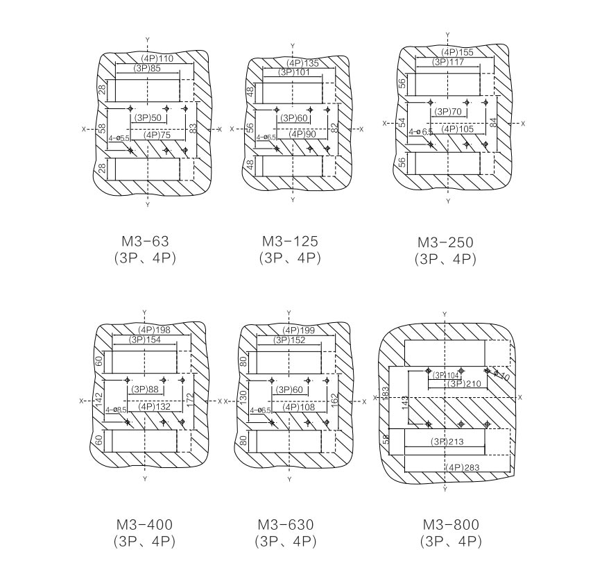
□ Plug in type of front board wiring
X-X Y-Y is the center of the circuit breaker
□ Fix the body of the circuit breaker master (back board wiringused) pedestal plug in wiring used on the installation board
□ Connection with the main circuit
a.The cross-sectional area which used for the connect wires mustbe adapted to the rated current table
| Rated Current (A) | 10 | 16/20 | 25 | 32 | 40 | 63 | 80 | 100 | 63/140 | 125 | 180/200 255 | 315 | 400 |
| Cross sectional Area (mm2) | 1.5 | 2.5 | 4 | 6 | 10 | 16 | 25 | 35 | 50 | 70 | 185 | 185 | 240 |
| Rated Current (A) | Cable | Copper row | ||
| Quantity | Section area (mm2) | Quantity | Size (mm) | |
| 500 | 2 | 150 | 2 | 30X5 |
| 630 | 2 | 185 | 2 | 40X5 |
| 700/800 | 2 | 240 | 2 | 50X5 |
b.Select the connecting terminal
M3 circuit breaker has four types of connecting terminal:
JGC type, JBG type, JBC type or JB type (Offered by users order), follows are the specifications.
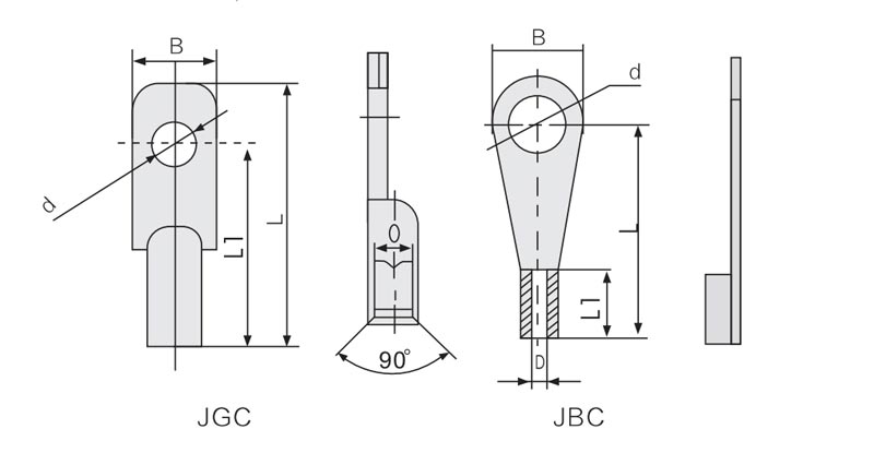
| Model | Rated current (A) | Corss-sectional Area (mm2) | Model of terminal | B | L | L1 | D | d |
| M3-63 | 10/16/20 | 2.5 | JBC2.5-8 | 15 | 24.5 | 8.5 | Φ2.6 | Φ8.2 |
| 25 | 4 | JBC4-8 | 13.4 | 20.4 | 9.2 | Φ2.8 | Φ8.2 | |
| 32 | 6 | JBC6-8 | 15 | 24.5 | 10 | Φ3.5 | Φ8.2 | |
| 40/50 | 10 | JBC10-8 | 15 | 24.5 | 11 | Φ4.5 | Φ8.2 | |
| 63 | 16 | JBC16-8 | 12.5 | 41 | 33.5 | Φ6 | Φ8.2 | |
| M3-125 | 10/16/20 | 2.5 | JBC2.5-8 | 15 | 24.5 | 8.5 | Φ2.6 | Φ8.2 |
| 25 | 4 | JBC4-8 | 13.4 | 20.4 | 9.2 | Φ2.8 | Φ8.2 | |
| 32 | 6 | JBC6-8 | 15 | 24.5 | 10 | Φ3.5 | Φ8.2 | |
| 40/50 | 10 | JBC10-8 | 15 | 24.5 | 11 | Φ4.35 | Φ8.2 | |
| 63 | 16 | JBC16-8 | 12.5 | 41 | 33.5 | Φ6 | Φ8.2 | |
| 80 | 25 | JBC25-8 | 14 | 46 | 38.5 | Φ7 | Φ8.2 | |
| 100 | 35 | JBC35-8 | 15.5 | 52 | 44.5 | Φ8 | Φ8.2 | |
| 125 | 50 | JBC50-8 | 17 | 54 | 45 | Φ10 | Φ8.2 | |
| M3-250 | 100 | 35 | JBC35-8 | 15.5 | 52 | 44.5 | Φ8 | Φ8.2 |
| 125/140 | 50 | JBC50-8 | 17 | 54 | 45 | Φ10 | Φ8.2 | |
| 160 | 70 | JBC70-8 | 21.6 | 61 | 52 | Φ11 | Φ8.2 | |
| 180/200/225 | 95 | JBC95-8 | 22 | 66 | 57 | Φ13 | Φ8.2 |
Note: M3-63, M3-125 the Specifition of current 10A,16A,20A adopt JBC2.5-8; Specification of 32A adopt JBC6-8; Specification of 40A,50A adopt JBC10-8 Wiring terminal.
c. The insulating sleeve must be installed on the terminal whenback board wiring
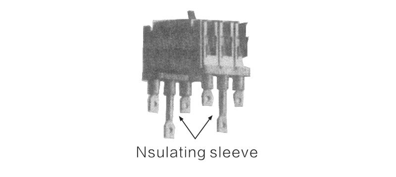
d. Use the bolts (bolts must be set into the flat pad and a springwasher) to connect with a well pressed wire and the conduct of circuit breaker, torque wrench andtighten the bolt, impose the size.
| Model | Specification of the bolts | Torque (N.m) |
| M3-63 | M8 | 6 |
| M3-125 | M8 | 6 |
| M3-250 | M8 | 6 |
| M3-400 | M10 | 10 |
| M3-630 | M12 | 14 |
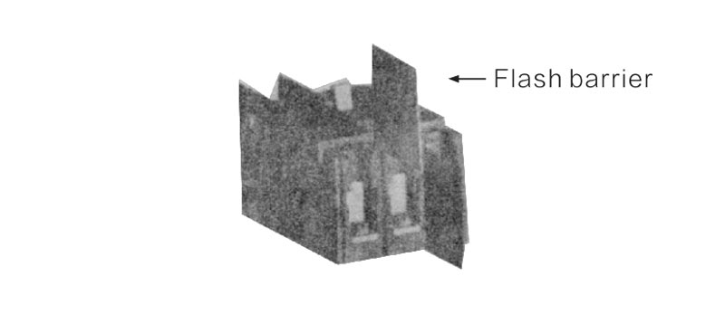
□ Nstall the flash barrier between the circuit breaker.
□ The electrical wiring of the internal accessories in the circuit breakera.
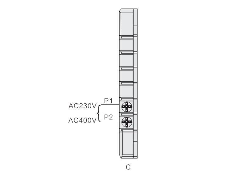
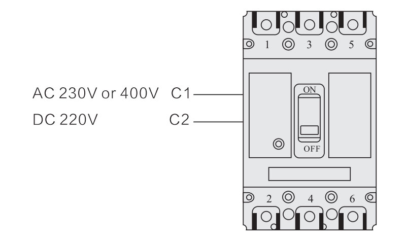
a. Under-voltage release according to the number of the connecting terminal in the Plug-in model, then connect it to the power (No need todistinguish between positive and negative when it is DC power)
Note: * When the user adopts the DC24V shunt release, the maximum length of the copper wire (the length of each of the two wires) must meet the requirements of the following table:
| Rated control power supply voltage Us (DC24V) | Input power | Copper wire length | |
| 1.5mm2 | 2.5mm2 | ||
| 100%Us | 50w | 150m | 250m |
| 85%Us | 50w | 100m | 160m |
b. Shunt release according to the number of the input wire, then connect it to thepower. No need to distinguish between positive and negative when it is DC power
c. Auxiliary contact and Alarm contact according to the number of output wires, connect them to the correspond circuit of the external control.
Note: F11,F12,F14 are the connecting terminal of auxiliary connect;
B11,B12,B14 are the connecting terminal of Alarm contact.
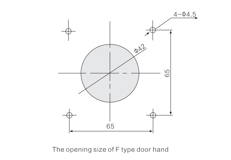
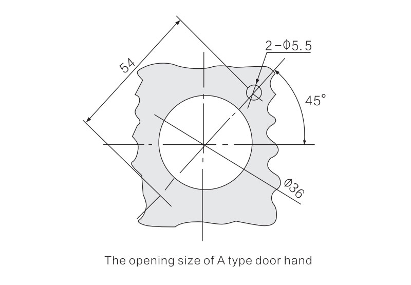
□ lnstall the Turning handle of operating mechanism
a. Before the Installation, there is already a hole for the door of operating handle switch, at the same time (the opening hinge distance from thecenter is not less than 100mm).
b. Fix the circuit breaker which have already install theoperating mechanism in the cover pass.
c. Fix the side-axis joystick in the hole of the operating mechanism.
d. Close the door which have already open the hole, adjust the location of the circuit breaker so that the center of the side-axis and the center of opening hole in the handle are in the same line.
e. Close the switch board doors which have already installed theturning handle, try to operate the handle. The handle should be aglity, when it is setted in the position of horizontal, the circuit breaker should switch on. when it is setted in the position ofvertical, the circuit breaker should be Switch off.
Product Choice
| Name | Details |
| Enterprise code | Shanghai Yuhuang Electric Co.,ltd |
| Product category | Moulded case circuit breaker |
| Design code | 3 |
| Current rank (Amp) | 125A,160A,250A,400A,630A,800A |
| Breaking capacity | L=economical type,M=standard type,H=high score type |
| pole | 3P,4P |
| Part NO. | 300 No part(Please see the release part NO.table) |
| Rated current | 10A~800A |
| Operation type | None=Manual direct operation P=Electric operation Z=Manual manipulation |
| Use NO. | None=Power distribution type breaker 2=Protect motor |
| N pole shape | Four poles products’ N polar form:A type:N polar do not install over-current release,and N polar does not open and close together with other three.B type :N polar do not install over-current release,and N polar opens and close together with other three polarsC type :N polar installs over-current release,and N polar opens and closes together with other three polars.D type :N polar installs over-current release,and N polar electrifies all the time, at the same time,N polar does not open and closes together with other three polars. |
| Writing type | None=None(front writing),R(Back board writing),PR(plug-in) |
Precautions
Operation
Check the following item before running
□ Check the wiring method if it is all correct.
□ Special check the input terminals (1,3,5) are connected with thepower line, and the output terminals (2,4,6) are connected with the load line.
□ Use the megger to test the circuit breaker between the phase-phase, phase-earth with insulation resistance.
□ Confirm that the connecting terminal and the fixed screw are all Fasten without any loosen.
□ Check if the circuit breaker has already installed the flash barrier.
□ The circuit breaker go with Under-voltage release, the release should be electricity, then allow the circuit breaker switch in.
Trying to operate
According to the each item of 4.1 are all confirmed without any abnormal situation, then you can try to operate the circuit breaker.
a.Pull the handles, the operation should be flexible.
b.The main circuit breaker must connect with the power, then press the botton of release, circuit breakers should release, and the operation handle must in the release location.
Running
lf you can meet the second points of 4.2, then put into operation.
After-sales service
This product is manufactured under perfect quality management. In the event of a failure, the warranty period and future service specialoperations are described below.
Warranty
lf the users comply the conditions of safekeeping and using and the seal of the circuit breaker is well. from the date of the product delivery, not more than 18 months. lf it has the quality problems that caused damage or can not be used normally, our company have the responsibility for repair or replacement.
However, as a result of the following reasons for failures, even in the warranty ,it also must paid for repair or replacement.
① Due to the use error, inappropriate conversion and maintenance.
② Exceed the standard of requirement.
③ After purchased, the circuit breaker dropped down during the installstion.
④ Earthquake, fire,lightning, abnormal voltage, and two other natural disasters.
After-sales service
① When the failure occurred, please contact with the supplier or the after-sales service department of the company.
② The repair and replacement in the warranty if it is the company's manufacturing problems, that caused the failure, our company have the responsibility of free charge of repair, as well as replacement.
③The repair or replacement after warranty, If the circuit break can still work, we can offer the customer repair and replacement with some charge.