As we are factory, we can guarantee our price is first- hand.
We have professional consultants to give you the most suitable solution.
Delivery time: 1-10 days after received the payment.
We have our own R&D team.
Support OEM/ODM.
MOQ : 1.
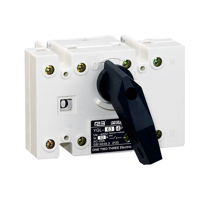
Product Details
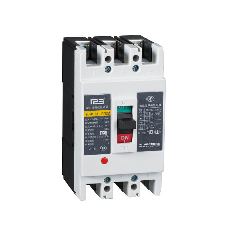
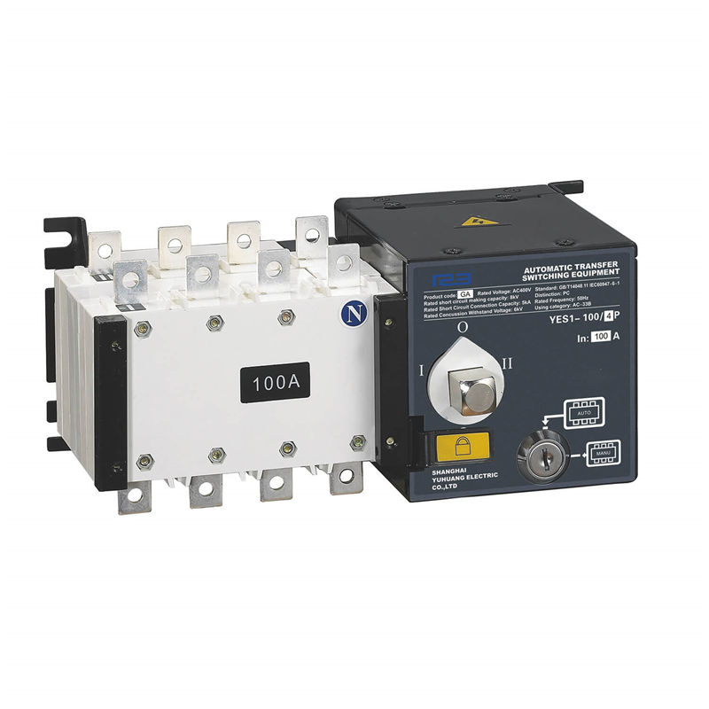
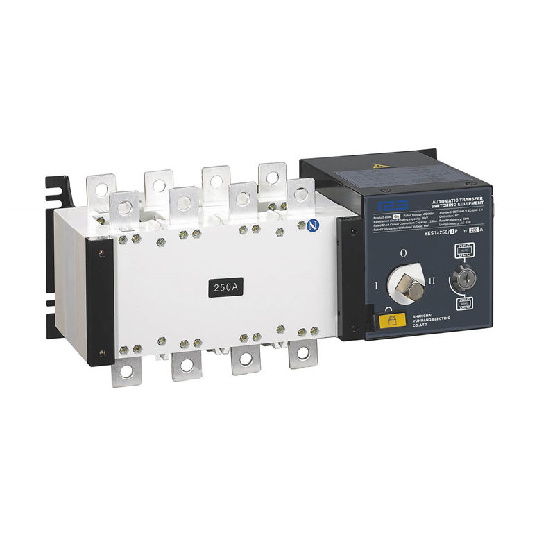
Rated current: 16A~3200A
Pole: 4P
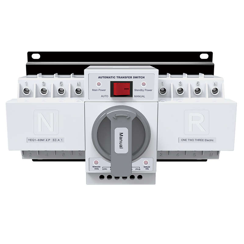
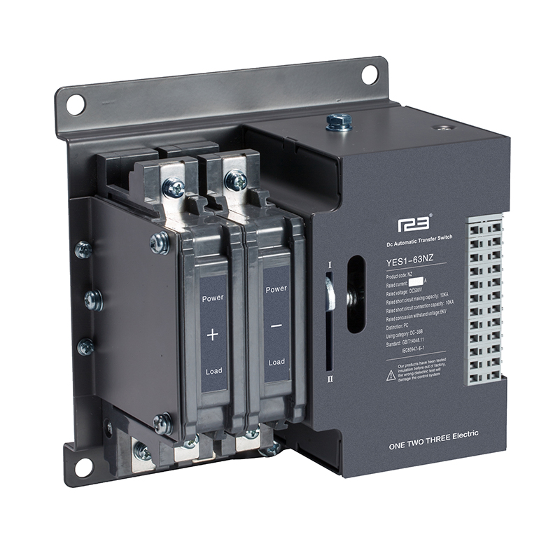
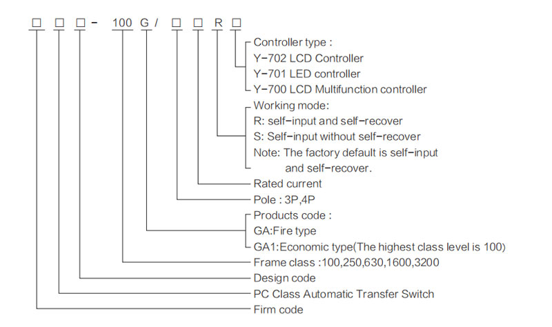
Automatic Transfer Switch (ATS) Manual Instruction YES1 series GA model
Notice:
Before you operate this Automatic transfer switch (hereinafter ATS),please read and understand these instructions carefully.
Dangerous
▲Before you install or operate the ATS,please read and understand these instructions carefully.Only the professional ATS personnel can carry out this installation,adjustment, repair and maintenance.
▲Many parts of the ATS, including printed circuit boards, when it work on-line voltage, cannot touch these parts. Use insulated tools only.
▲Do not touch the components which not protected.
▲Before maintenance the line of ATS, we should take the following preventive measures:
- Disconnect all power.
- Put a "prohibited closing" signs before the locate of the switch
- Switch to "0" position and then hang padlock.
Warning
Inconsistent with the line voltage:
Before Power and configuration for the ATS , we must ensure the line voltage is in the scope of the power supply voltage in the name plate of the ATS If the line voltage and power supply voltage range is different ,it will damage the ATS.Using it not according to the instructions it will damage the equipment.
Check and install
■ ATS delivery
Check and make sure the product is the ordering products.
■ Check the voltage
Check and make sure the voltage and the working voltage of the ATS.
Whether it is in the scope of the voltage.
■ Install the ATS
Install the ATS according this manual instruction.
Install all the external accessories.
■ Wiring the ATS
Connect the bus bar of the switch which coincided with the rated current.
Connect the control wire and outside indication well according to the manual instruction.
Product Parameters
Type and meaning
Main technology parameters
| Frame class | 100 | 250 | 1600 | 3200 | ||||||||||||||||||
| Agreed heating current Ith(A) | 63 | 100 | 160~3200 | |||||||||||||||||||
| Rated current In(A) | 16 | 20 | 25 | 32 | 40 | 50 | 63 | 80 | 100 | 125 | 160 | 250 | 400 | 630 | 800 | 1000 | 1250 | 1600 | 2000 | 2500 | 3200 | |
| Rated insulation voltage(Ui) | 690V | 800V | ||||||||||||||||||||
| Rated concussion withstand voltage(Uimp) | 8KV | |||||||||||||||||||||
| Rated working voltage(Ue) | AC400V | |||||||||||||||||||||
| Rated working current (le) | 16 | 20 | 25 | 32 | 40 | 50 | 63 | 80 | 100 | 125 | 160 | 250 | 400 | 630 | 800 | 1000 | 1250 | 1600 | 2000 | 2500 | 3200 | |
| Using category | AC-33B | AC-33iB | ||||||||||||||||||||
| Rated short-circuit connection capacity | 8KA | 26KA | 67KA | |||||||||||||||||||
| Rated short-time withstand current(Icw) | 5kA/30ms | 12.6kA/60ms | 32kA/60ms | |||||||||||||||||||
| Transfer time Ⅰ-Ⅱ or Ⅰ-Ⅱ | 2.5s | 0.6s | 1.2s | 1.8s | 2.4s | |||||||||||||||||
| Control voltage | DC24V, 48V, 110V, AC220V | |||||||||||||||||||||
| Rated frequency | Start | 20W | 325W | 355W | 400W | 440W | 600W | |||||||||||||||
| Norma | 62W | 74W | 90W | 98W | 120W | |||||||||||||||||
| Weight(kg) 4Pole | 3.4 | 6 | 7.6 | 15.8 | 16.8 | 36 | 36 | 37 | 38.6 | 55 | 61 | 67 | ||||||||||
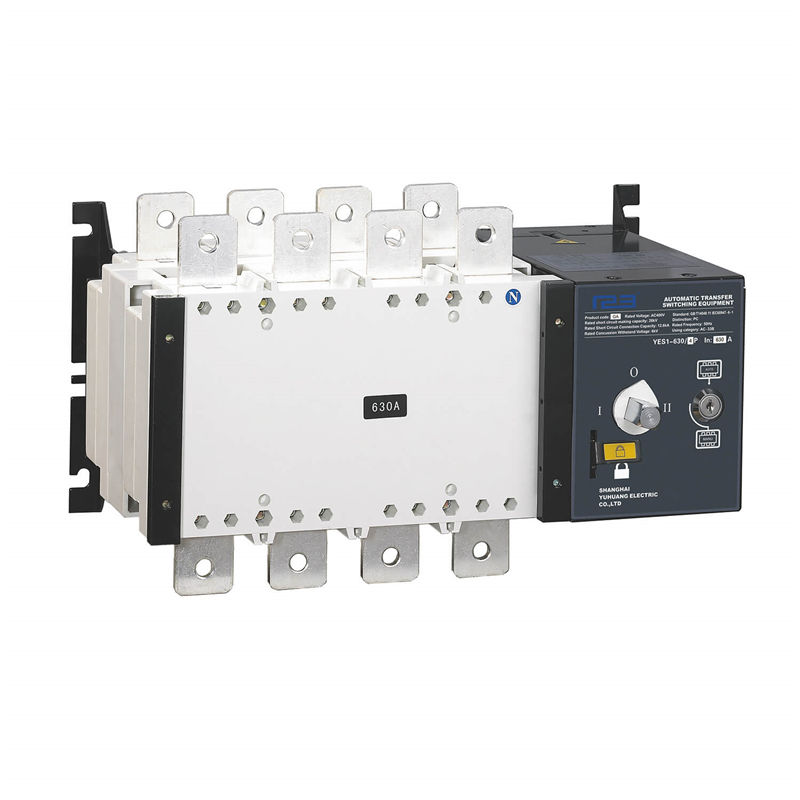
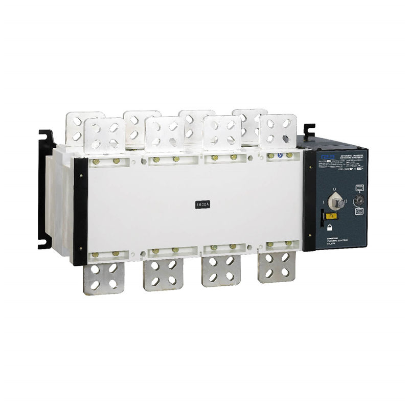
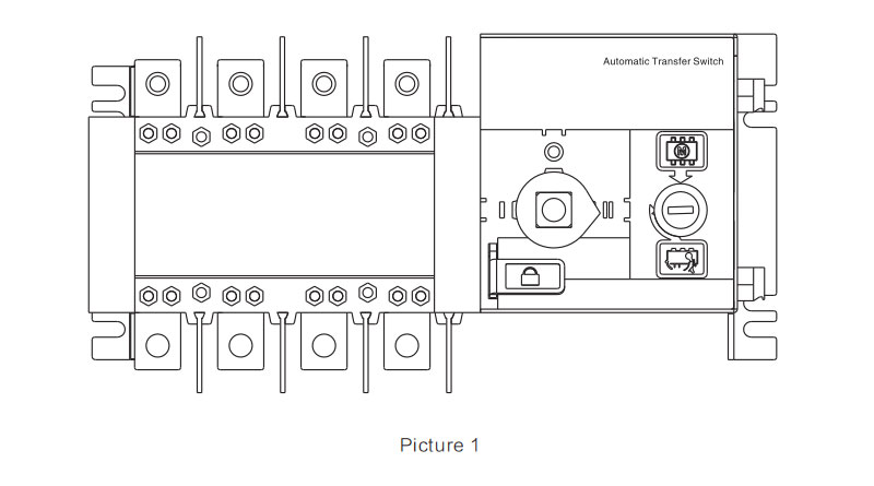
Switch structure explain
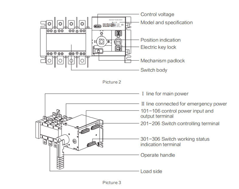
① Electric key lock:Control the inside controlling line power supply of the switch,when the Electric lock open,the switch could be operated automatically and remotely, when the electric lock closed,the switch could be operated by handle only.
② Operating handle: When operate the switch by the operating handle, the electric lock must be closed.
③ Mechanic padlock:When inspection,firstly turn the switch to the"0" position by operationhandle,then pull the padlock mechanism and close the padlock,then the inspection can be arranged:(Pull the mechanism padlock will cut off the inside controlling power supply of the switch.The switch couldn't be inelectric position and also couldn't be manual operation.
④ Position indication:It means the position of the switch working estate (Ⅰ,0,Ⅱ)
⑤ Controlling voltage: AC220V
Outline and installation dimensions
16A~1600A installation diagram ( 2 input 1 output )
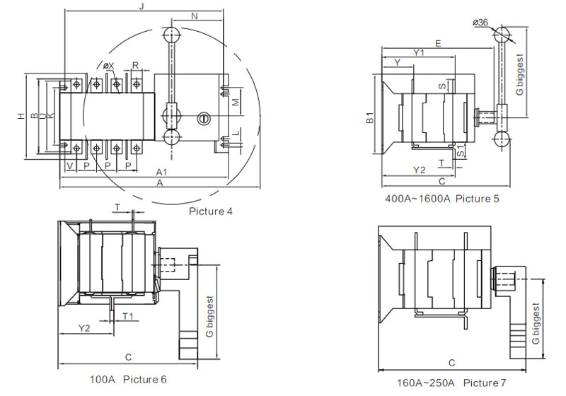
16A~1600A installation dimensions( 2 input 1 output )
| Specification | Total dimension | Switch installation | Connection terminal | ||||||||||||||||||||||
| A | A1 | B | B1 | C | E | G | H | J | K | L | M | N | P | R | S | S1 | T | T1 | U | V | ΦX | Y | Y1 | Y2 | |
| 16~100A | 270 | 245 | 110 | 103 | 170 | 142 | 115 | 146 | 226 | 84 | 7 | 44 | 81 | 30 | 14 | 18 | 23 | 2.5 | 5 | 103 | 12 | 6 | 40.5 | 92 | 67.5 |
| 125~160A | 348 | 305 | 147 | 142 | 224 | 190 | 144 | 185 | 284 | 102 | 7 | 49 | 91 | 36 | 20 | 25 | 37 | 3.5 | / | 127.5 | 19 | 9 | 56 | 127.5 | 127.5 |
| 250A | 411 | 368 | 170 | 142 | 224 | 190 | 144 | 200 | 347 | 102 | 7 | 49 | 91 | 50 | 25 | 29 | 40 | 3.5 | / | 141.5 | 28 | 11 | 56 | 130 | 130 |
| 400A/3P | 525 | 374 | 234 | 222 | 305 | 268 | 250 | 290 | 354 | 179 | 9 | 96 | 91 | 65 | 32 | 37 | 52 | 5 | / | 222 | 38 | 11 | 83 | 193 | 193 |
| 400A/4P | 585 | 435 | 234 | 222 | 305 | 268 | 250 | 290 | 415 | 179 | 9 | 96 | 91 | 65 | 32 | 37 | 52 | 5 | / | 222 | 38 | 11 | 83 | 193 | 193 |
| 630A/3P | 525 | 374 | 250 | 222 | 305 | 268 | 250 | 290 | 354 | 179 | 9 | 96 | 91 | 65 | 40 | 45 | 61 | 6 | / | 222 | 38 | 12 | 83.5 | 193.5 | 196 |
| 630A/4P | 585 | 435 | 250 | 222 | 305 | 268 | 250 | 290 | 415 | 179 | 9 | 96 | 91 | 65 | 40 | 45 | 61 | 6 | / | 222 | 38 | 12 | 83.5 | 193.5 | 196 |
| 800~1000A/3P | 785 | 520 | 328 | 250 | 390 | 326 | 360 | / | 496 | 220 | 11 | 115 | 84 | 120 | 60 | 64 | 88 | 8 | / | 250 | 56.5 | 13 | 109 | 254 | 254 |
| 800~1000A/4P | 1080 | 635 | 328 | 250 | 390 | 326 | 540 | / | 610 | 220 | 11 | 115 | 84 | 120 | 60 | 64 | 88 | 8 | / | 250 | 60.5 | 13 | 109 | 254 | 254 |
| 1250A/3P | 785 | 520 | 336 | 250 | 390 | 326 | 360 | / | 496 | 220 | 11 | 115 | 84 | 120 | 80 | 68 | 100 | 8 | / | 250 | 56.5 | 13 | 109 | 254 | 254 |
| 1250A/4P | 1080 | 635 | 336 | 250 | 390 | 326 | 540 | / | 610 | 220 | 11 | 115 | 84 | 120 | 80 | 68 | 100 | 8 | / | 250 | 60.5 | 13 | 109 | 254 | 254 |
| 1600A/3P | 785 | 520 | 336 | 250 | 390 | 326 | 360 | / | 496 | 220 | 11 | 115 | 84 | 120 | 80 | 68 | 108 | 10 | / | 250 | 56.5 | 13 | 110 | 255 | 255 |
| 1600A/4P | 1080 | 635 | 336 | 250 | 390 | 326 | 540 | / | 610 | 220 | 11 | 115 | 84 | 120 | 80 | 68 | 108 | 10 | / | 250 | 60.5 | 13 | 110 | 255 | 255 |
16A~1600A installation diagram ( 2 input 2 output )
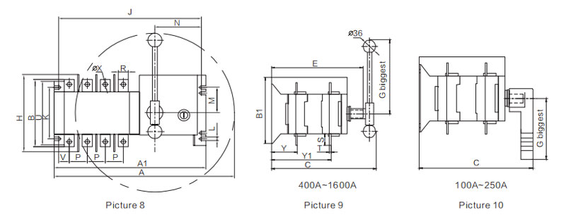
1000A~1600A installation diagram
16A~1600A installation dimensions ( 2 input 2 output )
| Specification | Total dimension | Switch installation | Connection terminal | |||||||||||||||||||
| A | A1 | B | B1 | C | E | G | H | J | K | L | M | N | P | R | S | T | U | V | ΦX | Y | Y1 | |
| 16~100A | 270 | 245 | 106 | 103 | 170 | 142 | 115 | 146 | 226 | 84 | 7 | 44 | 81 | 30 | 14 | 18 | 2.5 | 103 | 12 | 6 | 40.5 | 92 |
| 125~160A | 348 | 305 | 135 | 142 | 224 | 190 | 144 | 185 | 284 | 102 | 7 | 49 | 91 | 36 | 20 | 25 | 3.5 | 127.5 | 19 | 9 | 56 | 127.5 |
| 250A | 411 | 368 | 159 | 142 | 224 | 190 | 144 | 200 | 347 | 102 | 7 | 49 | 91 | 50 | 25 | 29 | 3.5 | 141.5 | 28 | 11 | 56 | 130 |
| 400A/3P | 525 | 374 | 234 | 222 | 305 | 268 | 250 | 290 | 354 | 179 | 9 | 96 | 91 | 65 | 32 | 37 | 5 | 222 | 38 | 11 | 83 | 193 |
| 400A/4P | 585 | 434 | 234 | 222 | 305 | 268 | 250 | 290 | 414 | 179 | 9 | 96 | 91 | 65 | 32 | 37 | 5 | 222 | 38 | 11 | 83 | 193 |
| 630A/3P | 525 | 374 | 250 | 222 | 305 | 268 | 250 | 290 | 354 | 179 | 9 | 96 | 91 | 65 | 40 | 45 | 6 | 222 | 38 | 12 | 83.5 | 193.5 |
| 630A/4P | 585 | 434 | 250 | 222 | 305 | 268 | 250 | 290 | 414 | 179 | 9 | 96 | 91 | 65 | 40 | 45 | 6 | 222 | 38 | 12 | 83.5 | 193.5 |
| 800~1000A/3P | 785 | 520 | 328 | 250 | 390 | 326 | 360 | / | 496 | 220 | 11 | 115 | 84 | 120 | 60 | 64 | 8 | 250 | 56.5 | 13 | 109 | 254 |
| 800~1000A/4P | 1080 | 635 | 328 | 250 | 390 | 326 | 540 | / | 610 | 220 | 11 | 115 | 84 | 120 | 60 | 64 | 8 | 250 | 60.5 | 13 | 109 | 254 |
| 1250A/3P | 785 | 520 | 336 | 250 | 390 | 326 | 360 | / | 496 | 220 | 11 | 115 | 84 | 120 | 80 | 68 | 8 | 250 | 56.5 | 13 | 109 | 254 |
| 1250A/4P | 1080 | 635 | 336 | 250 | 390 | 326 | 540 | / | 610 | 220 | 11 | 115 | 84 | 120 | 80 | 68 | 8 | 250 | 60.5 | 13 | 109 | 254 |
| 1600A/3P | 785 | 520 | 336 | 250 | 390 | 326 | 360 | / | 496 | 220 | 11 | 115 | 84 | 120 | 80 | 68 | 10 | 250 | 56.5 | 13 | 110 | 255 |
| 1600A/4P | 1080 | 635 | 336 | 250 | 390 | 326 | 540 | / | 610 | 220 | 11 | 115 | 84 | 120 | 80 | 68 | 10 | 250 | 60.5 | 13 | 110 | 255 |
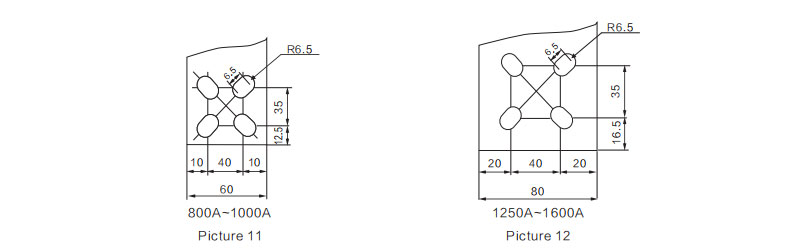
2000A~3200A installing dimensions
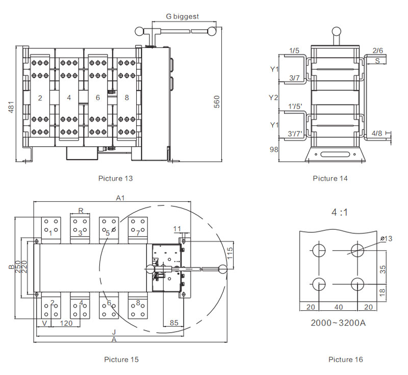
2000A~3200A installing dimensions
| Specification | A | A1 | B | G | J | R | S | T | V | Y1 | Y2 |
| 2000A/3P | 785 | 537 | 423 | 360 | 496 | 80 | 81 | 10 | 56 | 113 | 121 |
| 2000A/4P | 1080 | 651 | 423 | 540 | 610 | 80 | 81 | 10 | 72 | 113 | 121 |
| 2500A/3P | 785 | 537 | 433 | 360 | 496 | 80 | 81 | 15 | 56 | 118 | 116 |
| 2500A/4P | 1080 | 651 | 433 | 540 | 610 | 80 | 81 | 15 | 72 | 118 | 116 |
| 3200A/3P | 785 | 537 | 443 | 360 | 496 | 80 | 81 | 20 | 56 | 123 | 111 |
| 3200A/4P | 1080 | 651 | 443 | 540 | 610 | 80 | 81 | 20 | 72 | 123 | 111 |
Manual instruction
1. GA1 type Economic ATS manual instruction(Fit for rated current:16A-100A)
Note: Please pay attention to Main power and Emergency power phase sequence corresponding relation when you are wiring the switch.
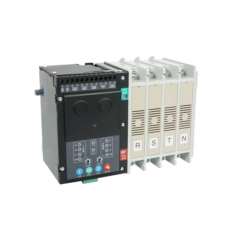
2. GA type fire type ATS manual instruction(Fit for rated current:16A-3200A)
Note: Please pay attention to Main power and Emergency power phase sequence corresponding relations when you are wiring the switch.
GA type ATS using manual (Fit for 16A-3200A fission type)
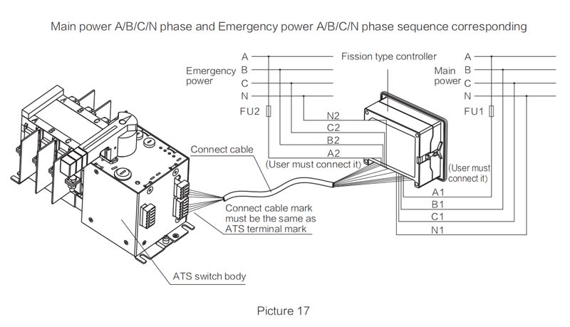
Note: Controller manual instruction please to see the Y-701/702 user manual
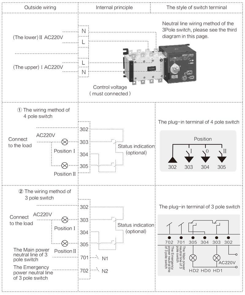
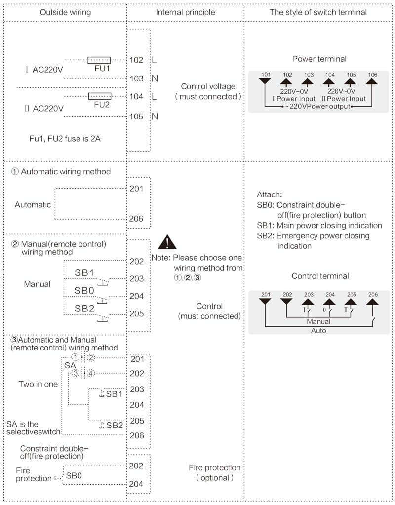
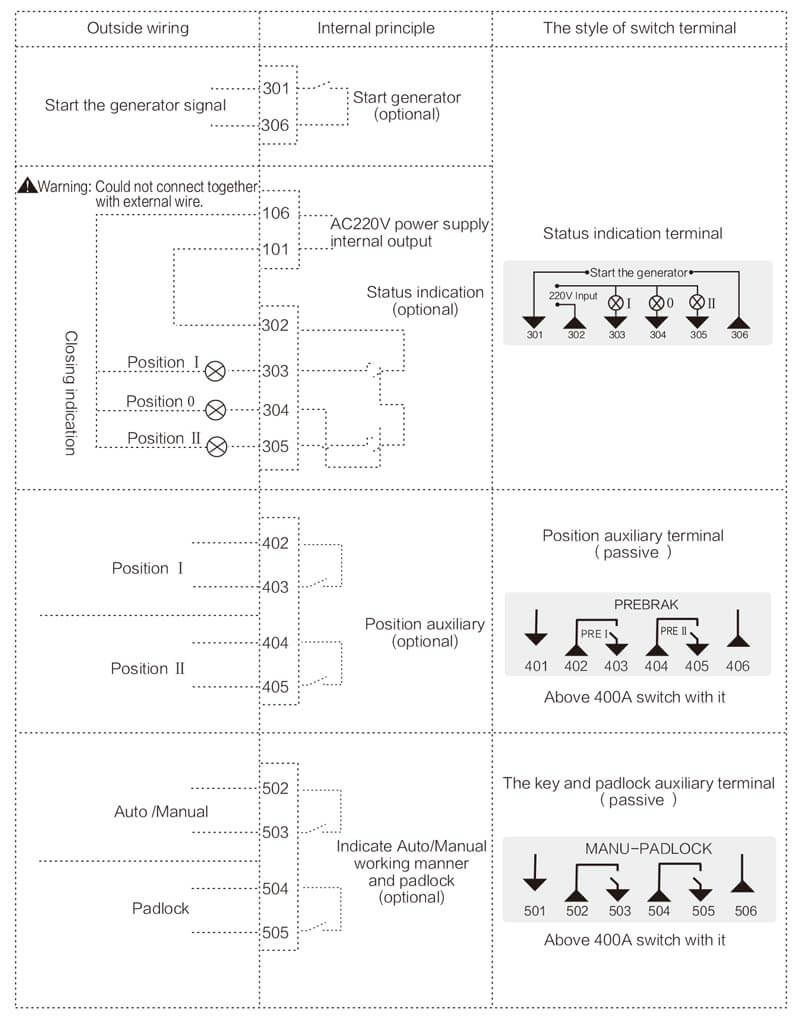
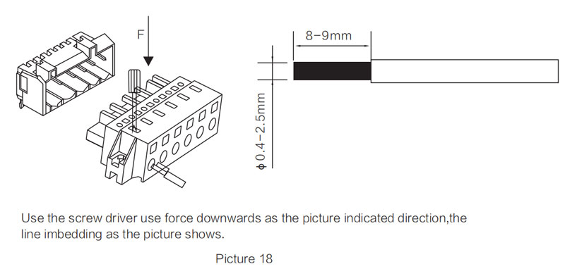
Method of terminal connection
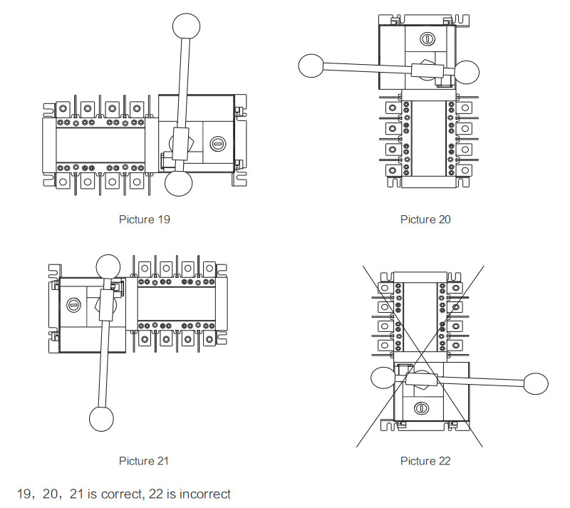
Correct installation method of the switch
Product Choice
| Model | Type | ||||
| YES1-100GA | YES1-250GA | YES1-630GA | YES1-1600GA | YES1-3200GA | |
| Rated Current(Amp) | 16A~100A | 125A~250A | 315A~630A | 800A~1600A | 2000A~3200A |
| Rated Insulation Voltage | 690V | 800V | |||
| Rated Impulse with Stand Voltage(KV) | 8 KV | ||||
| Rated Working Voltage | AC400V | ||||
| Usingzation Category | AC - 33B | AV - 33iB | |||
| Rated Short-Time with Stand Current | 5KA/30ms | 10KA/60ms | 12.6KA/60ms | 21KA/60ms | |
| Transfer Time | 2.5s | 0.6s | 1.2s~2.4s | ||
| Control Power Voltage | DC24V、48V、110V AC220V | ||||
| Vote Number | Double Throw | ||||
| Wiring Manner | Panel Mounting | ||||
| Pole | 4P | ||||
| Weight(kg) | 3.4 | 7.6 | 16.8 | 38.6 | 67 |
Precautions
Wiring methods of the switch
1. The primary wiring diagram to see the picture 3.
2. The control power is derived from normal power, emergency power cand N phases.
3. Ⅰ andⅡ line control power AC220V connected with terminal 102~103,104~105 respectively, 102 and 104 are normal power and emergency power live line respective.
4. Terminal 101,106 are act as signal lamp to control the power supply. Note:101 and 106 couldn't be connected with any other lines.
5. When above (under) input line, under (above) terminalⅠand Ⅱ line A, B, C phases will be connected with copper lines or lines acting as output.
The instruction of debug the switch
1. Connect the normal power (Ⅰ),emergency power(Ⅱ) to the corresponding copper bar respectively;
① Automatic debugging
Normal power supply with electric,emergency power supply with Electric,switchⅠline switch on
Normal power supply without electric,emergency power supply with electric,switch Ⅱswitch on
Normal power supply with electric,switchⅠ line switch on
(Refer to the switch panel white indicating arrowhead)
② Remote debugging
Press the bush button SB1,then the switchⅠline switch on
Press bush button SB2,then the switch Ⅱ line switch on
③ Automatic/Remote(Manual)debugging
When dial the function selection switch to the automatic position: the switch should act as the ① item required
When dial the function selection switch to the remote (manual) position, the switch should act as the ② item required
2. When the switch is in the position of switch onⅠline or Ⅱ line,the signal lamp on the panel should indicate correspondingly;
3. After finished the debugging,close the power supply firstly,and transfer the switch to the "0" position by handle. (Middle position,refer to the switch panel white indicating arrowhead).