As we are factory, we can guarantee our price is first- hand.
We have professional consultants to give you the most suitable solution.
Delivery time: 1-10 days after received the payment.
We have our own R&D team.
Support OEM/ODM.
MOQ : 1.
Product Details
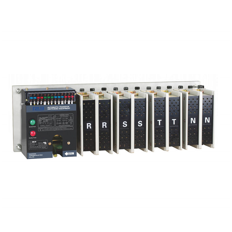
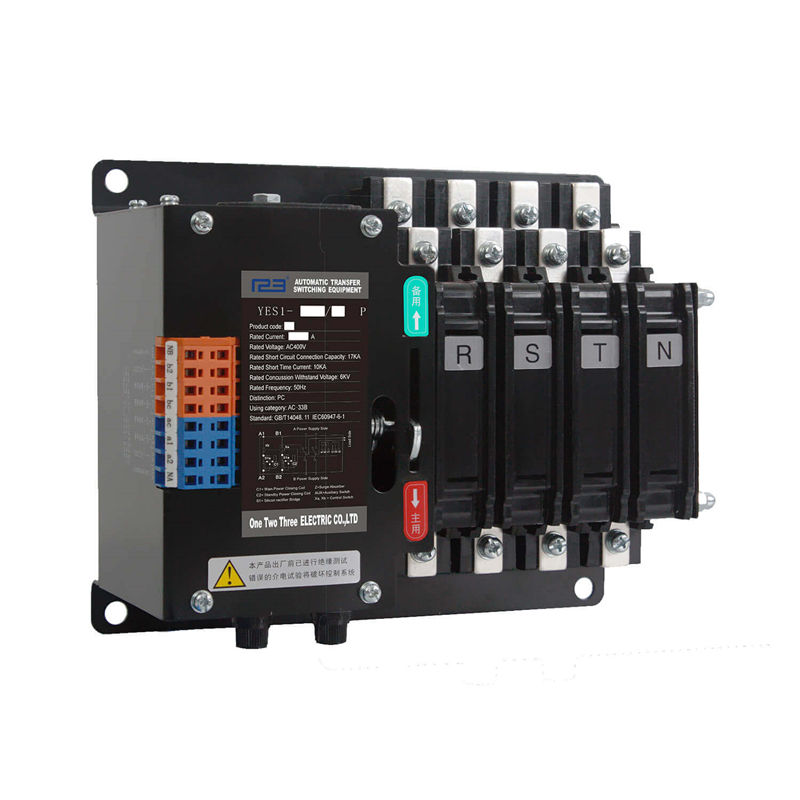
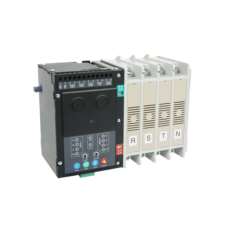
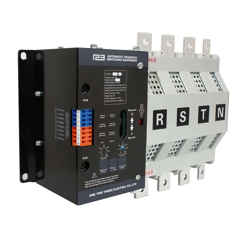
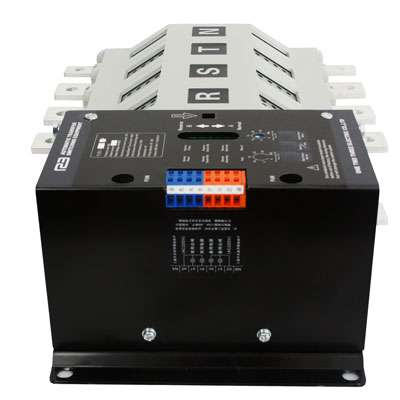
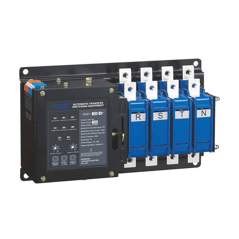
With contact terminal system and the switch can be transfer when the load is running.Integral and two working position.The main and backup power sources can be the power grid, the self-starting generator set, the battery group and so on.
YES1-32NA Automatic Transfer Switch is mainly used for the 16A~630A primary and secondary loads specified, is widely used in an important place to supply power continuously.Such as fire protection, post and telecommunications, Communication, hospitals, hotels, urban rail transit, high-rise buildings, industrial assembly lines, television stations, etc.
Rated Current:16A ~ 630A
Pole:2p,3p,4p
Automatic transfer switch Instruction manual
Description
The components of the product undergo strict aging screening, and the finished product is powered on for 72 hours. After passing the inspection, It can be packaged.Thereby ensuring the reliability and safety of the product. This product is mainly used for the primary and secondary loads specified by the state, and is widely used in an important place to supply power continuously. Such as fire protection, post and telecommunications, Communication, hospitals, hotels, urban rail transit, high-rise buildings, industrial assembly lines, television stations, etc. The main and backup power sources can be the power grid, the self-starting generator set, the battery group and so on.
Working conditions
1.Ambient air temperature: ambient air temperature -5°C to +40 °C, and the 24-hour average temperature value does not exceed+35 °C. with ambient air temperatures above +40°C or below-5°C , Users should consult with the manufacturer.
2.Air humidity: when the maximum temperature is +40 degrees, the relative humidity is not more than 50%.Monthly maximum relative humidity90%.It can tolerate the influence of humid air at sea and allow at lower temperatures.With higher relative humidity, special measures should be taken fortheoccasional condensationproducedby temperature changes.
3.Installation height: the installation site is not more than 2000 meters above sea level. For higher height ,considering the decrease in dielectric strength and cooling effect of air at higher altitudes. Users should consult with the manufacturer.
4.Pollution level: the environmental pollution level of the installation site is level 3.
5.Installation Category: Installation Category is IV.
6.Mounting inclination: The product is fixedly installed in the cabinet with a maximum inclination of ±22.5°.
7.Arcing distance: The arcing distance is 80mm when AC is 400V. The arcing distance can be ignored when using below 125Ampere. 2.8 Use category:AC-33B
Product structure
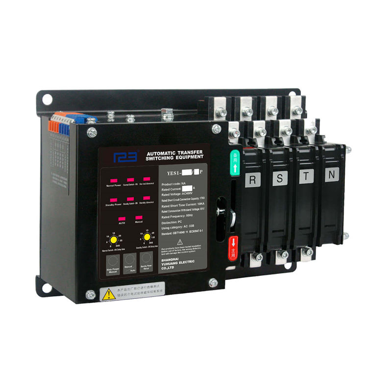
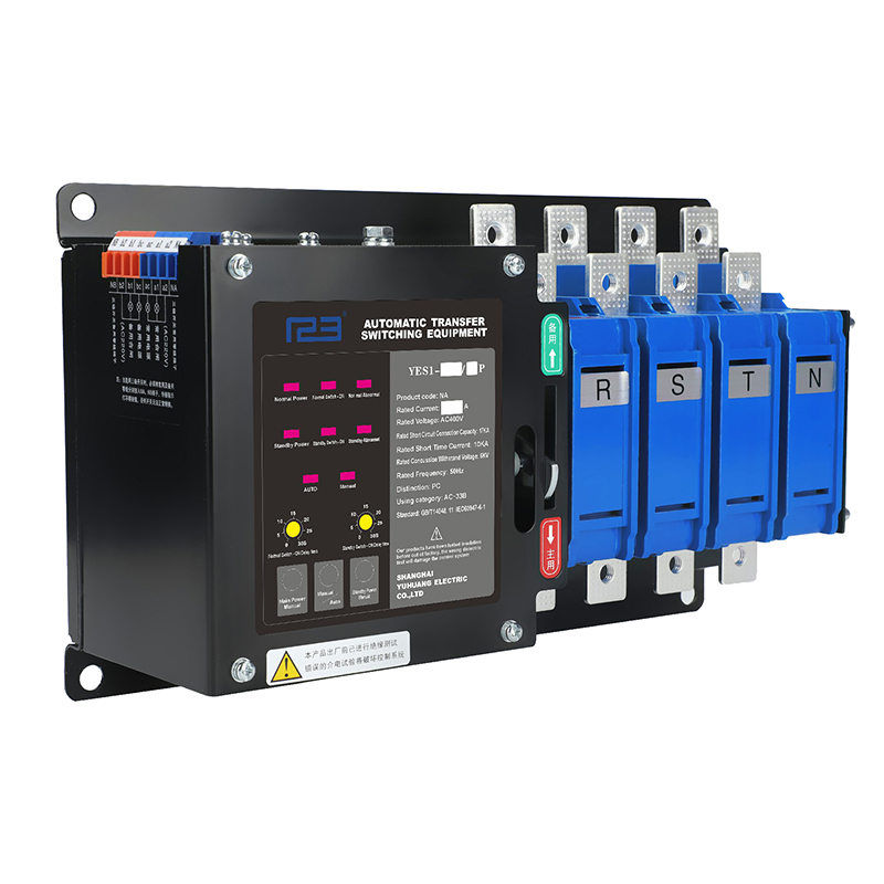
The product consists of two parts: switch body and intelligent ATS controller. The switch body with an electrical and mechanical interlock. The closing indication is used as an indicator of the isolation function. The product used solenoid actuate, double wire loop DC pulse operation, The operation power of the conversion controller adopts the line voltage 220V of main power and standby power supply.No need to additional control power.
Product Parameters
Product model and meaning
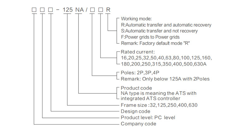
Product introduction
NA type automatic transfer switch with integrated ATS controller.The user only need to put in power, it can be work.
Label description
a. Normal Power: Normal Power normal indication
b. Standby Power: Standby Power normal indication
c. Normal Switch- On: Normal Power supply indication
d. Standby Switch -On: Standby Power supply indication
e. Normal Abnormal: Normal Power with Over-voltage, Under-voltage or Phase loss indication
f. Standby Abnormal: Standby Power with Over-voltage, Under-voltage or Phase loss indication
g. Auto:In automatic mode.
h. Manual:In manual mode.
i. Normal Switch-on Delay time and Standby Switch-on delay time:It can be transfer delay in 0~30second.
j. Button operation Main Power Manual: Normal Power supply in manual mode. Manual/Auto: Manual mode and automatic mode transition Standby Power Manual: Standby Power supply in manual mode.
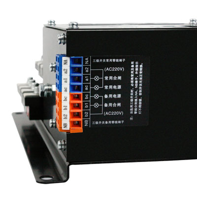
Terminal wiring instructions
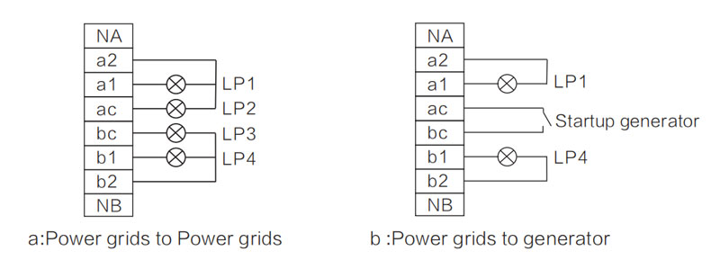
① NA:It is neutral terminal of normal power for 3poles ATS;
② LP1:Normal Power supply indicator light;
③ LP2:Normal Power indicator light;
④ LP3:Standby Power indicator light;
⑤ LP4:Standby Power supply indicator light;
⑥ NB:It is neutral terminal of standby power for 3 poles ATS;
Outline and installing dimensions
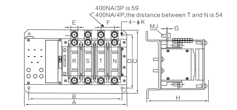
| Type | Dimension | |||||||||||||
| A | B | C | D | E | F | G | H | J | K | |||||
| 2P | 3P | 4P | 2P | 3P | 4P | |||||||||
| 32A | 216 | 243 | 270 | 196 | 223 | 250 | 184 | 167 | 12 | 27 | 3 | 110 | 5 | 9 |
| 125A | 237 | 274 | 311 | 217 | 254 | 291 | 184 | 167 | 20 | 37 | 3 | 110 | 8 | 9 |
| 250A | / | 322 | 372 | / | 302 | 352 | 290 | 200 | 20 | 49 | 5 | 146 | 8 | 10 |
| 400A | / | 352 | 402 | / | 332 | 382 | 294 | 200 | 30 | 59 | 6 | 146 | 10 | 10 |
| 630A | / | 352 | 412 | / | 332 | 392 | 294 | 200 | 35 | 59 | 6 | 146 | 12 | 10 |
Product technical characteristics
| Specification | 16/20 25/32A | 32/40/50/63 80/100/125A | 160/180 200/250A 3 | 250/315 50/400A | 500/630A | |
| Rated control power supply voltage (V) | AC220 | AC220 | AC220 | AC220 | AC220 | |
| Rated control supply current (A) | 3.5 | 3.5 | 7 | 7 | 7 | |
| Rated short-time withstand current (KA) | 10 | 10 | 10 | 10 | 10 | |
| Service life | Mechanical | 20000 | 20000 | 17000 | 17000 | 17000 |
| Electrical | 6000 | 6000 | 6000 | 6000 | 6000 | |
| Operating cycle (1minute /times) | 10 | 10 | 12 | 15 | 15 | |
Product Choice
| Model | Type | |||||||
| YES1-32NA | YES1-125NA | YES1-400NA | ||||||
| Rated Current (Amp) | 16A~32A | 40A~125A | 160A~630A | |||||
| Rated Control Current (Amp) | 5A | 7A | ||||||
| Rated Short Circuit Current (Amp) | 10A | |||||||
| The Rated Impulse with Stand Voltage(KV) | 8 | |||||||
| Usingzation Category | AC - 33B | |||||||
| Mechanical Life | 20000 | 17000 | ||||||
| Electric Life | 6000 | |||||||
| Pole | 2P | 3P | 4P | 2P | 3P | 4P | 3P | 4P |
| Weight(kg) | 4.2 | 4.7 | 5.2 | 5 | 5.5 | 6.5 | 18.5 | 20.5 |
| Operating Cycle(S/Time) | 10 | |||||||
Precautions
Product installation and wiring
The work in the installation and commissioning of the product shall be carried out by professionals or those who have knowledge of the switchgear. Corresponding protection and precautions must be taken into account during operation. The main circuit of the switch must be wired in such a way that the leads are not subjected to any pressure or force.Before installation and commissioning, checking that the switch is not damaged or any other hazardous environmental impact, and it also should check whether the thread is loose due to transportation.Remove dirt, especially the dirt on the surface of the insulationparts .When connecting the primary circuit, it should be noted that the phase sequence of the normal power and standby power must be the same.When connecting the secondary circuit control loop, it should be strictly in accordance with the wiring diagram in instruction manual ,while paying attention to the control power supply voltage level, the switch must be installed with good grounding.
Pre-commissioning of products
Considering personal safety and switching speed, the debugging handle is only used for debugging. Users is not allowed use the debugging handle with load operation. Anditisnotallowedusewhenthearc extinguishing device is not installed. When debugging, the switch is operated with the debugging handle .To observe the close of the main contact and running conditions. All are no abnormal situation, then the ATS switch can be work.
1.After debugging controller and part of mechanical ,the controller and electrical part can be adjustedof the power-on debugging, the load is prohibited during the debugging process.
2.Put in the normal power into the products, the normal power indicator is light up, and then put in the standby power ,the standby power indicator is light up. and press the "Manual/Auto" button is placed in the manual position, Then press the "main power manual" button, The ATS will transfer to Main power quickly,The normal power indicator and external connecting indicator lamp is light up.Press the "standby power Manual", The ATS will transfer to Standby power quickly, The standby power indicator and external connecting indicator lamp is light up.
3.The“Manual/Auto”buttonis placed in the automatic position , delay time of normal power and standby power are adjusted to the appropriate value. The normal power supply is disconnected first, and the indicator of normal power Switch on is flashed on.When reached the setting of delay time value, The ATS will quickly switch to standby power supply automatically.The standby powerindicator and external connectingindicatorlamp is light up.When themainpoweris return,the ATS will switch to Normal power supply, the indicator of standby power switch on is flashes, the ATS will quickly transfer to the normal power supply, The normal powerindicator and external connecting indicator lamp is light up.
Use of products
1.In normal using, the controller should be placedintheautomatic position, The ATS is in the automatic control mode, The controller monitors both the main power and the backup power simultaneously and displays status. When the main power source has failure, such as power cut,under-voltage, over-voltage, or phase loss ,The ATS will transfer to Standby power automatically.The power delay time is in 0~30 second.When the main power return, the ATS will transfer from Standby power to Main power automatically.The controller is provided with a light-emitting diode to indicate condition of switch and power supply.
2.If you do not want the ATS switch automatically, or When other manual operations are required, you should set the controllerinManual position. When it is in Manual mode, the ATS is not transfer automatically.
3.When the ATS is in automatic mode,if the main power supply and the standby power supply are in normal condition.TheATSwillgive priority to connecting the main power supply to the load.
Common faults and solutions
When the product does not work or work abnormally, first check the following points:
a. Is the switch body and the controller connected good or not? Is the connection correct?
b. Is the power turned on?
c. Is the controller in manual mode?
d. Is the voltage normal?
e. Is the switch body and the controller of main and standby power inputs opposite?
f. Is the fuse intact?
g. Is the debug line too long when debugging? Is the wire diameter too thin?
h. Whether to distinguish between neutral line N, phase line and PE ground line during debugging?
After-sales service
This series of dual power automatic switch is a high-tech product developed by our company using the latest technology. It is high reliability and guarantee, In the operation, abnormal phenomena may occur. If the problem cannot be solved according to the above points, please contact our after-sales service department.