As we are factory, we can guarantee our price is first- hand.
We have professional consultants to give you the most suitable solution.
Delivery time: 1-10 days after received the payment.
We have our own R&D team.
Support OEM/ODM.
MOQ : 1.
Product Details
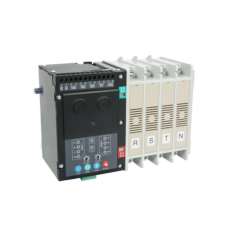
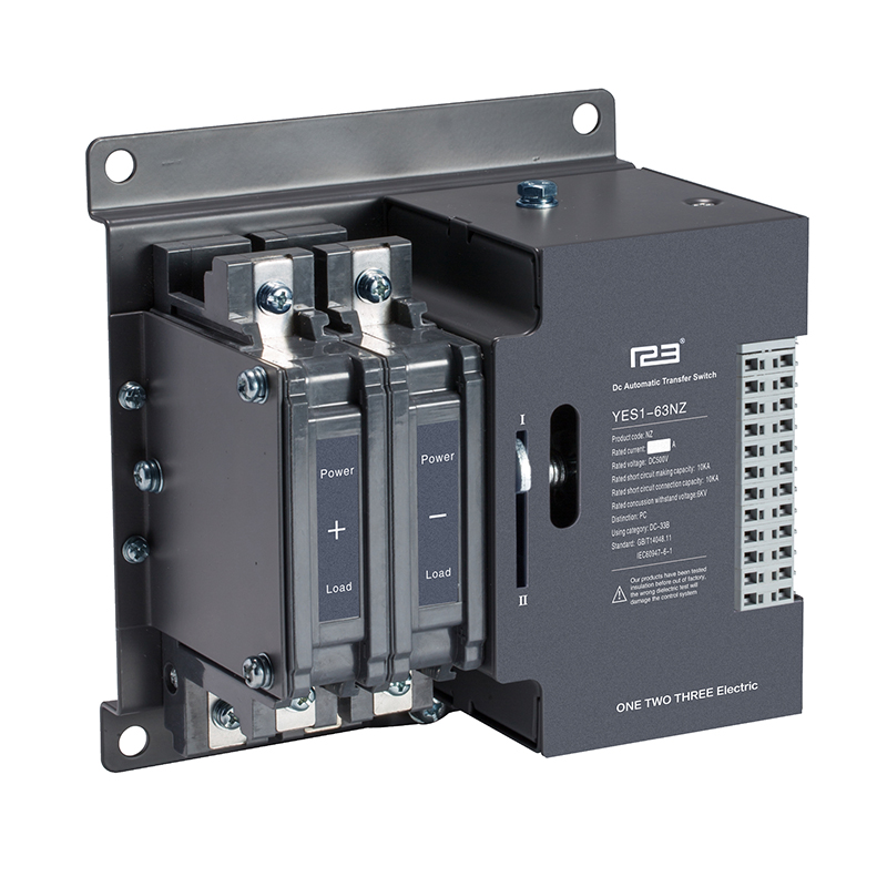
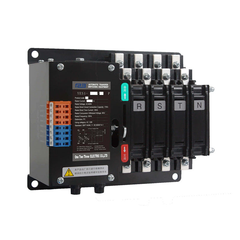
consists of switch ontology and intelligent controller. The switch body has electrical and mechanical linkage. uses electromagnetic drive, double coil dc pulse operation, the conversion controller's working power supply USES the main power supply, the standby power supply line voltage 220V alternating current, does not need to add the control power supply.
Rated current:630A~3200A
Pole:3P,4P
Overview
This series of automatic transfers switch is a high-tech product developed by our company with the latest technology.
It conforms to the standards of GB14048.1, GB/T14048.11, and also conforms to the "code for fire prevention of high-rise civil buildings", "code for fire prevention of building design", "emergency lighting design guide", "code for electrical design of civil buildings" and so on.
The parts and components of the products are strictly aged and screened. The finished products are electrified and stored for 72 hours continuously. Finally, they can be released from the factory after passing the loading inspection. Thus guaranteed the product reliable
Working conditions
1. Ambient air temperature: ambient air temperature ranges from -5℃ to +40 ℃, and the 24-hours average temperature does not exceed +35 ℃. Users should check with manufacturer when ambient air temperature above +40℃ or below -5℃ .
2. atmospheric humidity: when the highest temperature is +40℃, the relative humidity is not more than 50%, and the maximum monthly relative humidity is 90%, which can withstand the influence of the humid air at sea, and can allow higher at lower temperature!Relative humidity, for temperature change occasionally produced condensation should be taken special measures.
3. installation height: the elevation of installation site shall not exceed 2000m. For higher elevations, consult with the manufacturer to allow for reduced dielectric strength and cooling of the air.
4. pollution level: the environmental pollution level of the installation site is level 3.
5. installation category: installation category IV.
6. installation inclination: the product shall be fixed in the cabinet with the maximum inclination of ±22.50.
7. arc distance: at ac 380V, arc distance is 80mm. At ac 660V, the arc distance is 100mm. 2.8 use category: AC-33IB.
Product structure
The product consists of switch ontology and intelligent controller. The switch body has electrical and mechanical linkage.
The product uses electromagnetic drive, double coil dc pulse operation, the conversion controller's working power supply USES the main power supply, the standby power supply line voltage 220V alternating current, does not need to add the control power supply.
Product Parameters
Product model
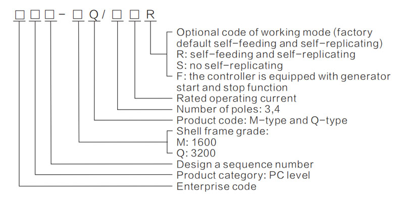
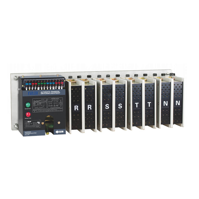
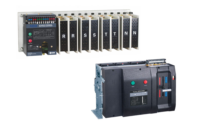
Introduction of m-type products
1. M type (630 A - 1600 A)
2. M product body electrical schematic diagram:
| Number | Parts Mark | Parts Name |
| 1 | BD | Rectifier bridge |
| 2 | LS1,LS2,LS3 | limit switch |
| 3 | CC | closing coil |
| 4 | MG | AC contactor |
3. Technical characteristics of M-type products
| Rated current | 630A | 800A | 1000A | 1250A | 1600A | |
| Rated control power supply voltage (V) | AC220 | |||||
| Rated control power supply current (A) | 16 | |||||
| Rated short-time withstand current (KA) | 32 | |||||
| Type of use | AC-33iB | |||||
| Working life | Mechanical | 2000 | 2500 | |||
| Electrical | 1000 | 500 | ||||
| Operating cycle (s/time) | 15 | 20 | 25 | |||
3. M- type Product appearance and installation size
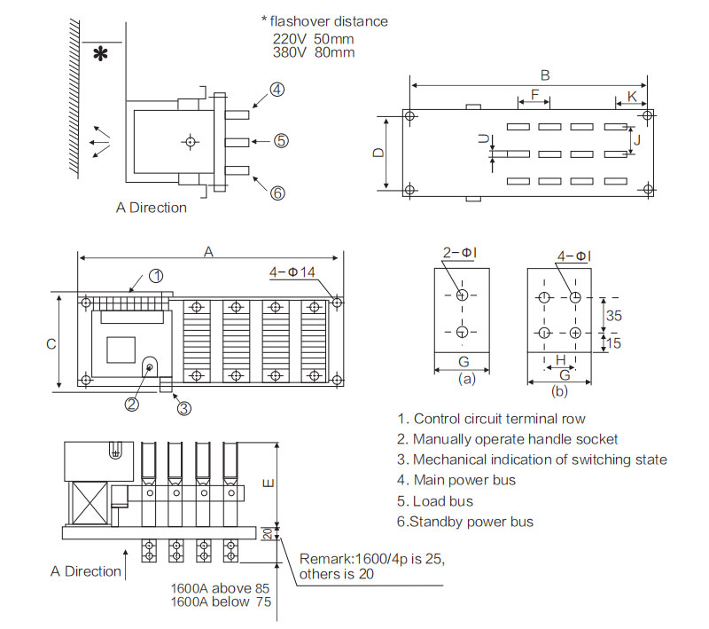
| Rated current | Size | ||||||||||||
| A | B | C | D | E | F | G | H | I | J | K | |||
| 3P | 4P | 3P | 4P | ||||||||||
| 630A | 530 | 600 | 490 | 560 | 280 | 210 | 250 | 90 | 30(a) | / | 12 | 75 | 75 |
| 800A | 90 | 40(a) | / | ||||||||||
| 1000A | 90 | 45(a) | / | ||||||||||
| 1250A | 90 | 55(a) | / | ||||||||||
| 1600A | 640 | 750 | 580 | 710 | 130 | 75(a) | 40 | 14 | 70 | 76 | |||
When M type product manual debugging, use the special strength lever, forced down switching direction, hear this closing lock "cough up" in the body of a ring, can release lever, otherwise cause switching does not reach the designated position, Phase deficiency in the main circuit, Check whether the main contact is in place according to the upper and lower closing indicators to determine as shown in the figure below:
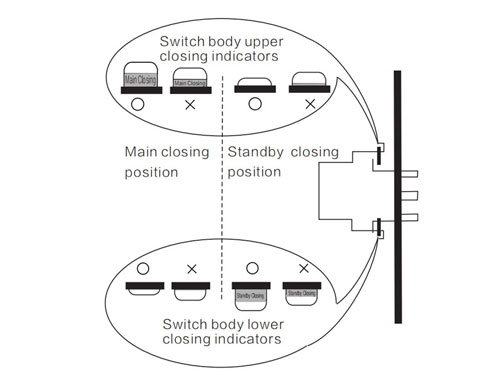
Closing status indication
Ο Right position
× Wrong Position
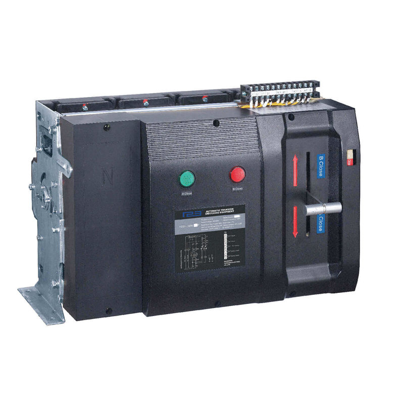
Introduction of q-type products
1 Q type (630A - 3200A)
① Both closing and disconnecting are operated by an electromagnetic coil.
② Simple structure and convenient maintenance.
③ Large contact capacity, stable and reliable new movable contact, strong overload capacity.
④ The redundant conductive part is eliminated, structure is simple and has a long life.
⑤ Independent double-arc extinguishing chamber structure is adopted on the main and standby power sides to prevent short circuit caused by arc fundamentally.
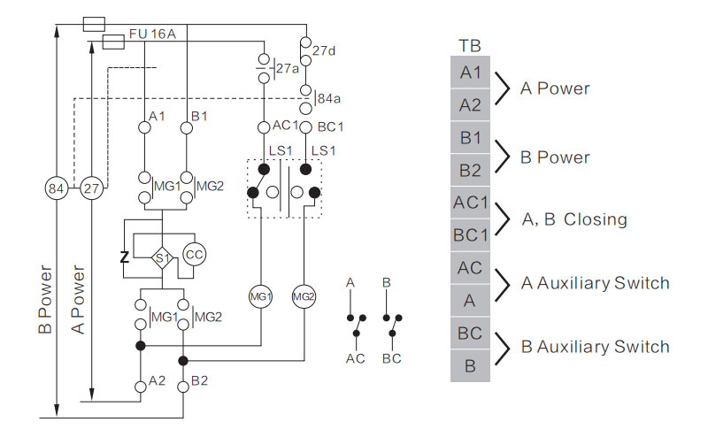
2. Q- type product body electrical schematic diagram:
3. Q - type Technical characteristics
| Rated current | 630A | 800A | 1000A | 1250A | 1600A | 2000A | 2500A | 3200A | |
| Rated control power supply voltage (V) | AC220 | ||||||||
| Rated control power supply current (A) | 16 | ||||||||
| Rated short-time withstand current (KA) | 50 | ||||||||
| Type of use | AC-33iB | ||||||||
| Working life | Mechanical | 2000 | 2500 | 1500 | |||||
| Electrica | 1000 | 500 | |||||||
| Operating cycle (s/time) | 15 | 20 | 25 | 50 | 100 | ||||
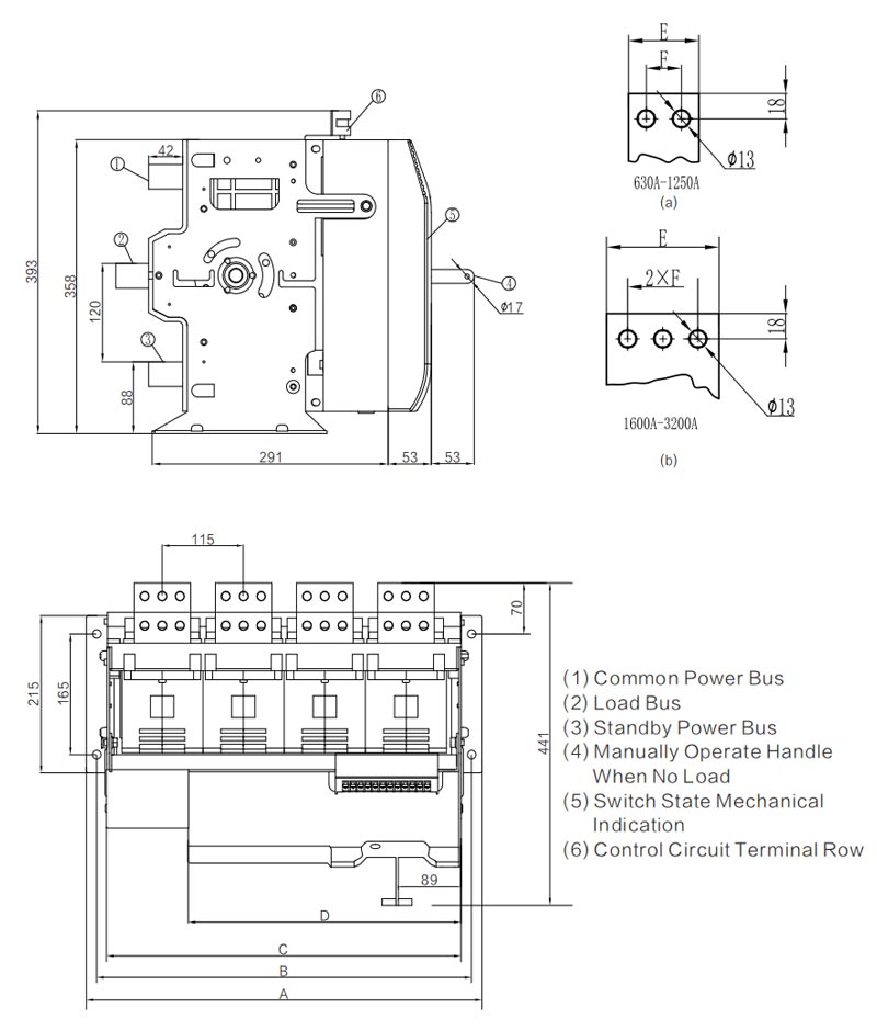
4. Q- type Product appearance and installation size
| Code | Pole | 630A | 800A | 1000A | 1250A | 1600A | 2000A | 2500A | 3200A |
| A | 3P/4P | 445(3P) / 561(4P) | |||||||
| B | 3P/4P | 415(3P) / 631(4P) | |||||||
| C | 3P/4P | 384(3P) / 502(4P) | |||||||
| D | 386 | ||||||||
| E | 45 | 50 | 60 | 80 | |||||
| F | 25 | ||||||||
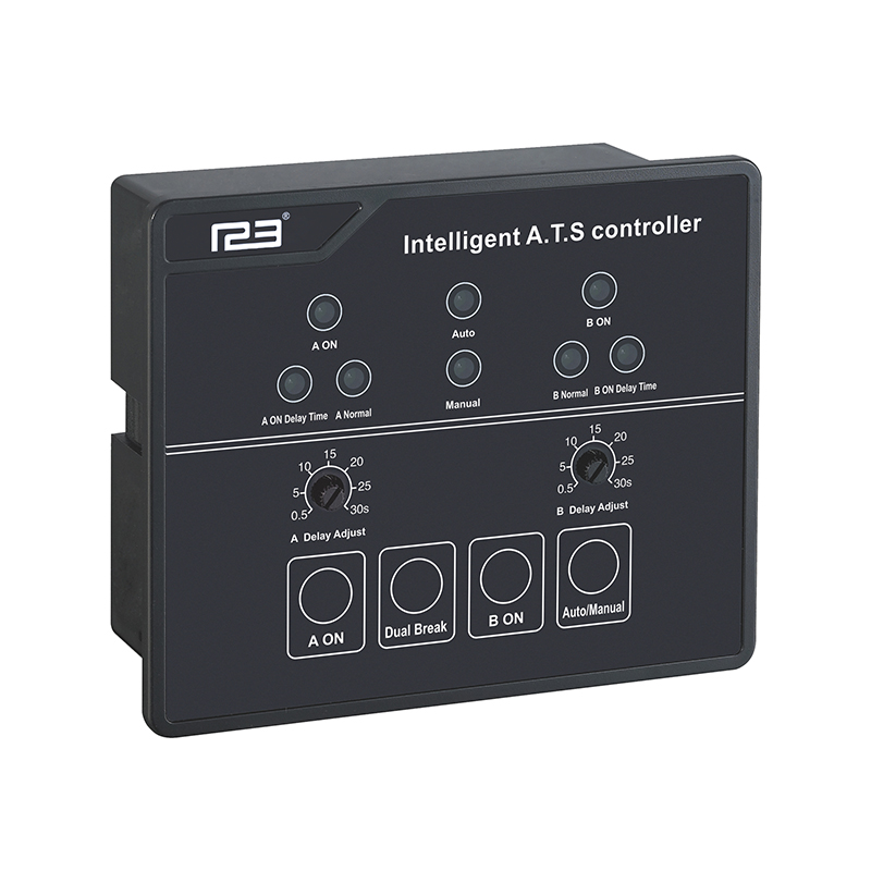
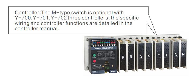
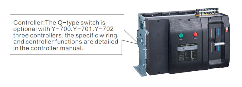
Intelligent controller introduction
According to the market demand, our company has developed a variety of product controllers. M-type and q-type products can be equipped with Y- 700, Y-701 and Y-702 controllers. For controller function and wiring mode, please refer to controller specification.
Product Choice
| Model | Type | |||||||||||||||||||||||||
| YES1-630M | YES1-800M | YES1-1000M | YES1-1250M | YES1-1600M | YES1-3200Q | |||||||||||||||||||||
| Rated Current(Amp) | 630A | 800A | 1000A | 1250A | 1600A | 630A | 800A | 1000A | 1250A | 1600A | 2000A | 2500A | 3200A | |||||||||||||
| Rated Control Current(Amp) | 12 | 16 | ||||||||||||||||||||||||
| Rated Short Circuit Current(Amp) | 32 | 120 | ||||||||||||||||||||||||
| The Rated Impulse with Stand Voltage(KV) | 8 | 8 | ||||||||||||||||||||||||
| Usingzation Category | AC - 33iB | AC - 33iB | ||||||||||||||||||||||||
| Mechanical Life | 25000 | 25000 | ||||||||||||||||||||||||
| Electric Life | 500 | 500 | ||||||||||||||||||||||||
| Pole | 3P | 4P | 3P | 4P | 3P | 4P | 3P | 4P | 3P | 4P | 3P | 4P | 3P | 4P | 3P | 4P | 3P | 4P | 3P | 4P | 3P | 4P | 3P | 4P | 3P | 4P |
| Weight(kg) | 37 | 42.5 | 39 | 46 | 41 | 48 | 48 | 57 | 60 | 67 | 39 | 44.5 | 40 | 47 | 41 | 48.5 | 42 | 50 | 45 | 54 | 58 | 68 | 59.5 | 70 | 61 | 72 |
| Operating Cycle(S/Time) | 15 | 20 | 25 | 15 | 20 | 25 | ||||||||||||||||||||
Precautions
Product installation and wiring
All the work in the installation and debugging of the product should be carried out by professionals and those who have known about the switch equipment. The corresponding protection and prevention measures must be considered in the work. The wiring mode of the switch main circuit must make the lead not subject to any pressure or strong effect.
Before installation and debugging, check whether the switch is free of damage or any other harmful environmental impact, and check whether the loose thread head is caused by transportation; Clean up the dirt, especially the dirt of the insulation table, when connecting the primary circuit should pay attention to the phase sequence of the main and backup power supply must be consistent, when connecting the secondary control circuit should strictly follow the wiring diagram listed in the manual, and pay attention to the voltage level of the control power supply, switch installation must have a good grounding.
Debugging before product operation
Considering personal safety and fast switching, the debugging handle is only used for debugging. Users should not use the debugging handle with load. Not allow load operation without proper arc extinguishing device. During debugging, use the debugging handle to operate the switch and observe the closure of the main contact. If there is no abnormality, turn on the power and observe the operation of the switch.
1. Commissioning of controller and electrical part after correct adjustment of the mechanical part, commissioning on the controller and electrical part can be carried out. No load is allowed during debugging.
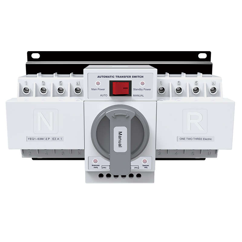
2. put main power supply into the panel and the normal indicator light of common power supply is on, and the standby power supply is put into successively.Panels normal standby power indicator light, middle manual position automatic/manual button, click the commonly used or smell products close this experience quickly switch to the common power, commonly used to smell and corresponding external indicator will light up at the same time, to click on the standby power close to smell product off this experience quickly switch to the standby power, standby switching and the corresponding external indicator will light up at the same time.
3. among the control panel there is automatic/manual button to set time and standby time is commonly used in the automatic position to appropriate values, disconnect common power supply first, commonly used electrical switching delay lights ablaze, arrival time delay setting product close this experience quickly switch to the standby power, standby switching and the corresponding external indicator will light up at the same time, put in common power, standby switching delay lights ablaze, arrival time delay value product switch this experience quickly returned to the common power supply, common closing and corresponding external indicator light lit at the same time (this project is not applicable to the self-turn not self - compound mode).
Use of products
1. during normal use, the controller shall be set in the "automatic" position under the automatic control mode. The product controller shall monitor the main power supply and the standby power supply at the same time and display the product operation state. When the main power supply fails, under-voltage, over-voltage and lack of equal fault, the product automatically converts the load from the main power supply to the standby power supply after "standby power delay"; If the main power supply is restored to normal, it will pass!Main electrical delay time (0 to 30 s adjustable) automatically after returning from standby power load to the main power supply (self-turn not self - compound mode products when standby power supply is normal, even if the main power supply back to normal, also keep the product load connected with standby power, will not load from the standby power supply return to the main power supply when abnormal standby power, to load from the standby power supply return to the main power supply), the controller panel is equipped with leds indicate the switch and the status of the power supply.
2. if automatic switch conversion is not desired, or other manual operation is required, the controller shall be put into the "manual" position. Manual switches are no longer automatically converted but manually converted.
3. when the product changes from "manual" to "automatic", if the main power supply and standby power supply are normal, the self-turn self- compound products and the self-turn not self - compound mode products shall be connected to the main power supply and load first.
Common faults and troubleshooting
When the product does not work or the action is abnormal, first check the following points:
1. Is the switch body connected with the controller loose? Is the connection correct?
2. Is the power on?
3. Is the controller in manual state?
4. Is the voltage normal?
5. Is the switch body opposite to the main and backup power input of the controller?
6. Fuse is intact?
7. When debugging, is the debugging line too long? Is the wire diameter too thin?
8. During test, is N line differentiated from phase wire and PE grounding wire?
After-sales service
This product is a mature product include designed, installed and inspected, but it also will have abnormal phenomena during operation. If malfunction can't be solved according to the above table, please contact our after-sales service department.